Do you have a question about the Panasonic SB-MAF7000PU and is the answer not in the manual?
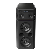
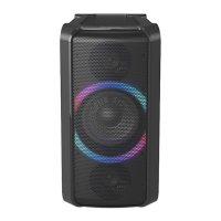
Details specifications for the main speaker units, including type, impedance, dimensions, and mass.
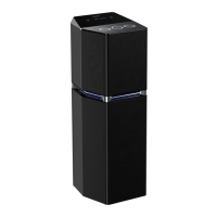
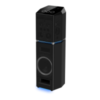
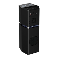
Details specifications for the subwoofer unit, including type, impedance, dimensions, and mass.
Lists specific disassembly steps for main speaker components like front panel, tweeter, and woofer.
Lists specific disassembly steps for subwoofer components like front panel and subwoofer speaker.
Identifies screw types used for SB-MAF7000PU/GS and SB-MAG7000PU/GS models.
Identifies screw types used for SB-MAW7000PU/GS subwoofer model.
Step-by-step guide to remove the front panel from the main speaker units.
Procedure for removing the tweeter speaker unit from the main speaker.
Procedure for removing the woofer speaker unit from the main speaker.
Steps to remove the lighting wire circuit board assembly from the main speaker.
Steps to remove the front panel from the subwoofer unit.
Procedure for removing the subwoofer speaker unit.
Steps to remove the lighting wire circuit board assembly from the subwoofer.
Diagram showing electrical connections for tweeter and woofer speakers.
Diagram illustrating the wiring connections for the subwoofer speaker.
Exploded view showing the location of cabinet parts for main speaker units.
Exploded view showing the location of cabinet parts for the subwoofer unit.
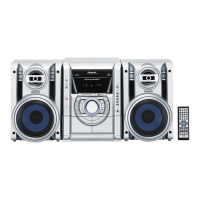
Illustrates how the product is packaged, including accessories and protective materials.
Lists replacement parts for SB-MAX7000GS speakers, including part numbers and quantities.
This document is a service manual for a range of Panasonic speaker systems, specifically the SB-MAF7000PU/GS, SB-MAG7000PU/GS, SB-MAW7000PU/GS, and SB-MAX7000PU/GS models. It provides detailed information for experienced repair technicians on the specifications, disassembly, assembly, wiring connections, and replacement parts for these speaker systems.
The manual describes various speaker units designed for audio output. The SB-MAF7000PU/GS and SB-MAG7000PU/GS models are standard speakers, while the SB-MAW7000PU/GS is a subwoofer speaker. The SB-MAX7000PU/GS appears to be a complete speaker system that includes both standard speakers and a subwoofer, as indicated by its packaging diagram showing multiple speaker units. These systems are designed to reproduce sound, with the standard speakers handling a broader frequency range and the subwoofer specializing in low-frequency sounds (bass). The inclusion of "Lighting Wire P.C.B. Assembly" in the disassembly instructions suggests that some models incorporate lighting features, enhancing the aesthetic or functional aspects of the speakers.
The manual provides specific technical specifications for the different speaker types:
Speakers (SB-MAF7000PU/GS, SB-MAG7000PU/GS):
Subwoofer Speaker (SB-MAW7000PU/GS):
Notes on Specifications:
The wiring connection diagrams further detail the internal electrical configuration. For the standard speakers (SB-MAF7000PU/GS, SB-MAG7000PU/GS), the tweeter (SP1) is connected in series with a 2.7µF 50V capacitor, indicating a crossover network to filter frequencies, allowing higher frequencies to pass to the tweeter. The woofer (SP2) is connected directly to the speaker terminal. The subwoofer speaker (SB-MAW7000PU/GS) shows a direct connection for its super woofer (SP3) to the speaker terminal, implying that any necessary filtering for the subwoofer is handled externally or by an integrated amplifier not detailed in this specific wiring diagram.
While primarily a service manual, some usage features can be inferred:
The manual is explicitly designed for maintenance and repair, offering comprehensive guidance for technicians:
Overall, this service manual provides a robust framework for the professional maintenance and repair of Panasonic's speaker systems, ensuring safety, correct part replacement, and adherence to original design specifications.