Do you have a question about the Panasonic SC-HC4GK and is the answer not in the manual?
General guidelines for servicing, including lead dress and protective devices.
Procedure to check leakage current without applying power.
Procedure to check leakage current with power applied, using specific circuits.
Techniques to reduce component damage caused by electrostatic discharge (ESD).
Precautions for handling the laser diode to avoid hazardous radiation exposure.
Information about lead-free solder used in components and its properties.
Guidelines for using lead-free solder during repair work.
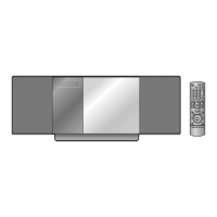
Information for service personnel to understand and service the model, including parts ordering.
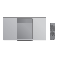
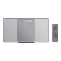
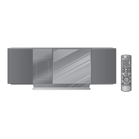
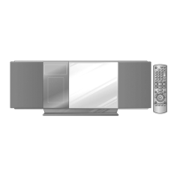
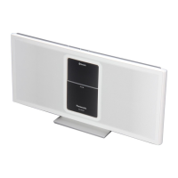
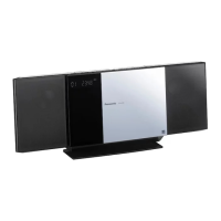
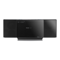
Description of key buttons on the main unit and their operations.
Details of remote control key button functions and operations.
Information on playing CDs, CD-Rs/RWs, and MP3 files, including limitations.
Summary table of service modes, player/remote buttons, and applications for checking.
Details of self-diagnostic and doctor modes, including FL display and key operations.
Instructions for removing the CD from the unit when the door is jammed.
Step-by-step instructions for removing the iPod from the unit.
Procedure for checking and repairing the Main PCB (Side A), involving several disassembly steps.
Procedure for checking and repairing the Main PCB (Side B), involving screw and cable detachment.
Voltage measurement values for various points on the CD Servo PCB during CD PLAY and STANDBY modes.
Voltage measurement values for various points on the D-AMP PCB under different modes.
Voltage measurement values for various points on the FL PCB under different modes.
Block diagram detailing the CD servo circuit, including ICs and signal paths.
Block diagram showing connections between main, tuner, iPod, FL, motor, and USB components.
Block diagram illustrating the D-AMP circuit and its connections to other parts of the main unit.
Block diagram showing the Panel 1/2, AUX/HP, IR, SMPS, and AC IN circuits.
Detailed schematic of the CD servo circuit, showing components and connections.
Part 1 of the main circuit schematic, showing microprocessor and related components.
Part 2 of the main circuit schematic, detailing power supply and amplifier sections.
Part 3 of the main circuit schematic, showing various input/output and control sections.
Part 4 of the main circuit schematic, illustrating audio and peripheral circuit connections.
Schematics for the FL display, Panel 1, and Panel 2 circuits.
Schematics for tuner, AUX/HP, IR, motor, position switch, and iPod switch circuits.
Schematics for the iPod circuit and AC IN circuit.
Schematic diagram of the D-AMP circuit, showing amplifier IC and related components.
Schematic diagram of the SMPS circuit, illustrating power supply components and connections.
Schematic diagram of the USB circuit, showing the USB controller and port connections.
Top and bottom views of the CD Servo PCB, showing component layout.
Component layout diagram for the Main PCB (1/2).
Component layout diagram for the Main PCB (2/2).
Component layout diagrams for Tuner, FL, Panel 1, Panel 2, AUX/HP, and IR PCBs.
Component layout diagrams for Motor, Position SW, iPod SW, iPod, and D-AMP PCBs.
Component layout diagrams for SMPS, AC IN, and USB PCBs.
Pin functions and descriptions for the RFKWMAHC4EP Micro Processor IC.
Pin functions and descriptions for the MN6627954AMA IC Servo Processor.
Pin functions and descriptions for the BA5948FPE2 IC 4CH Drive.
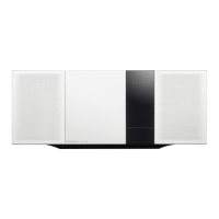
Exploded view showing the location of cabinet parts with corresponding reference numbers.
List of mechanical replacement parts with safety reference, part number, and description.
List of electrical replacement parts including PCBs, ICs, and transistors with their details.
| Brand | Panasonic |
|---|---|
| Model | SC-HC4GK |
| Category | Stereo System |
| Language | English |