SV-3700
MCONTENTS
Page
Page
INSTALLATION
sescsccsscsecsesielsccicssh
uc
stienteabeceeeencdicccesesesceystasteseccuess
2
WIRING
CONNECTION
DIAGRAMA.........cccssssescsssrseeseneenee
63,
64
CONNECTIONS
cascsenccsccadheciccisccccsbictideeescciseceltecucssedscasescuosievsetede
3
PRINTED
CIRCUIT
BOARDS
DIP
SWITCH
SETTINGS.
............ccsssscoscsscesccssscssssssccecceresssncsceseare
3
TROUBLESHOOTING
..........scccscssseeenssevees
a
LOCATION
OF
CONTROLS
-
4~8
KEY
POINTS
FOR
TROUBLESHOOTING
.........ccssseessetseecesenes
79
ACCESSORIES
wisssssscccivssccscsecsssavsssseasestosscnsentvodsoectustysresasesssoonssieass
8
ABOUT
THE
ERROR
RATE...........ccsscsssssececesensencesssssceessereneeaseees
80
SV-3700
DAT
MAINTENANCE
CHART
...........sccsssccecsooeeesees
9~14
ABOUT
THE
LEVEL
METER...........:sccsssccsssersseuscencessseessensesersase
80
DISASSEMBLY
INSTRUCTIONS
................
wa
15~19
ERROR
RATE
DISPLAY
FUNCTION
..........ccsscssssscessontcescsserseene
80
MEASUREMENTS
AND
ADJUSTMENTS
...........ccccccceoeees
20~25
ERROR
CODE
TABLE
...........cscssssccssesssscrsorssnsensersesseensensenmaccasees
81
TERMINAL
FUNCTION
OF
1078
wun...
ccecsessssseceseeseeeeeeres
26~36
REPLACEMENT
PARTS
LIST
..........scccsssessennesscsnssescenessoren
82~84
BLOCK
DIAGRAM
..........:cscsssccsssssscnssorsesesccensnseccecsersscesseens
37~40
EXPLODED
VIEWG........csocesecnssessoonssnesssnncressensenenssaseesoonssancon
85~90
INTERNAL
CONNECTION
OF
FL...........cccccseccessecsscsscesseacecesenes
41
REPLACEMENT
PARTS
LIST
............sscsscsssssseesorsccennersneseee
91~93
TERMINAL
GUIDE
OF
IC’S,
TRANSISTORS
PACKING
......ccssssscsreccsserscseccoees
AND.
DIODES
vcciscssnccccseciccscdesicecsncedscacsanvcsvcesersssucnscssssisteceess
42
RESISTORS
&
CAPACITORS
SCHEMATIC
DIAGRAM............sccscsscssseerssacecssenccessneeseeaseeees
43~62
Mi
INSTALLATION
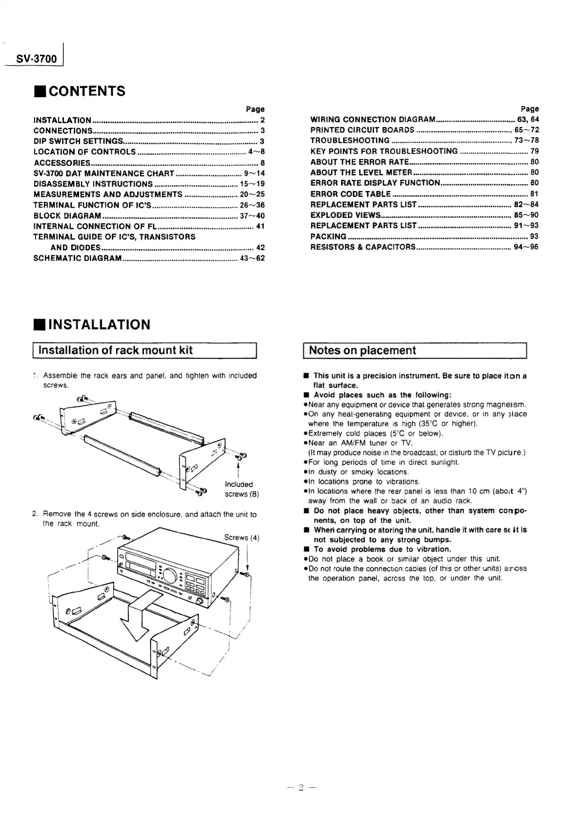
Installation
of
rack
mount
kit
1.
Assemble
the
rack
ears
and
panel,
and
tighten
with
included
screws.
Included
screws
(8)
2.
Remove
the
4
screws
on
side
enclosure,
and
attach
the
unit
to
the
rack
mount.
Screws
(4)
Notes
on
placement
@
This
unit
is
a
precision
instrument.
Be
sure
to
place
iton
a
flat
surface.
@
Avoid
places
such
as
the
following:
Near
any
equipment
or
device
that
generates
strong
magnetism.
@On
any
heat-generating
equipment
or
device,
or
in
any
place
where
the
temperature
is
high
(35°C
or
higher).
eExtremely
cold
places
(5°C
or
below).
@Near
an
AM/FM
tuner
or
TV.
(It
may
produce
noise
in
the
broadcast,
or
disturb
the
TV
picture.)
For
long
periods
of
time
in
direct
sunlight.
ein
dusty
or
smoky
focations.
e!n
locations
prone
to
vibrations.
@'n
locations
where
the
rear
panel
is
less
than
10
cm
(about
4")
away
from
the
wall
or
back
of
an
audio
rack.
@
Do
not
place
heavy
objects,
other
than
system
conpo-
nents,
on
top
of
the
unit.
@
When
carrying
or
storing
the
unit,
handle
it
with
care
se
itis
not
subjected
to
any
strong
bumps.
B
To
avoid
problems
due
to
vibration.
®@Do
not
place
a
book
or
similar
object
under
this
unit.
@Do
not
route
the
connection
caples
(of
this
or
other
units)
aiross
the
operation
panel,
across
the
top,
or
under
the
unit.
tw
|
 Loading...