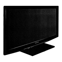
Do you have a question about the Panasonic TC-42PX24 and is the answer not in the manual?
Lists mechanical parts for replacement, including part numbers and descriptions.
Lists electrical components for replacement, detailing part numbers and specifications.
Illustrates the main functional blocks and connections within the TV system.
Details the first part of the A-Board schematic, covering the Nile-TCON section and related components.
Shows the third part of the A-Board schematic, focusing on specific circuit areas.
Displays the fifth part of the A-Board schematic, covering dedicated sections of the board.
Details the seventh section of the A-Board schematic, illustrating analog and video signal paths.
Provides essential instructions for conducting repairs and servicing safely and correctly.
Details the procedure for measuring leakage current when the unit is unplugged.
Explains how to measure leakage current with the unit powered on and connected.
Outlines techniques to prevent damage to sensitive electronic components from static electricity.
Explains the button sequence required to access the television's service mode.
Details the remote control key commands used for navigating and controlling service mode functions.
Lists the adjustable parameters available within the service mode, including sample data.
Important service mode feature for accessing diagnostic tools.
Important maintenance/configuration feature for data transfer via SD card.
Describes the process of transferring TV settings and data to an SD card.
Details the procedure for loading data from an SD card back into the TV set.
Troubleshooting step to diagnose issues with the IIC communication lines.
Explains how to access the self-check function for diagnosing IIC bus line issues.
Identifies specific components to check if an IIC bus line failure is indicated.
Correlates power LED blink patterns with specific error conditions and defective blocks.
Guides troubleshooting steps when the TV unit does not power on or display any indicators.
Provides diagnostic steps for troubleshooting issues where the screen remains blank despite power.
Describes potential localized screen failures and identifies the relevant PCBs for each area.
General section detailing various adjustment procedures for optimal performance.
Details the procedure for setting the Vsus voltage to LOW or HIGH after panel or A-board replacement.
Explains how to adjust the RF video sub contrast using a color bar pattern and service mode.
Guides the process of adjusting white balance settings using a color analyzer and service mode.
Presents a high-level overview of the TV's main functional blocks and their interconnections.
| Screen Size | 42 inches |
|---|---|
| Display Type | Plasma |
| Resolution | 1024 x 768 |
| Aspect Ratio | 16:9 |
| HDMI Ports | 2 |
| Component Video Input | 2 |
| Composite Video Input | 2 |
| Inputs | HDMI, Component, Composite |


 Loading...