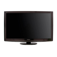
Do you have a question about the Panasonic TC-P50VT20 and is the answer not in the manual?
General instructions for conducting repairs and servicing safely.
Procedure to check leakage current with AC cord unplugged and jumpered.
Procedure to check leakage current with AC cord plugged in, using a resistor and capacitor.
Techniques to prevent damage to sensitive electronic components from static electricity.
Provides board names and their functions within the TV.
Steps to access the service mode using the remote and unit buttons.
Details the remote control commands for navigating service mode menus.
Instructions to access the service tool mode from the service mode menu.
Explains the indication of SOS history through LED blinking.
How to display and interpret power on time and count.
Procedure to check the IIC bus lines using the self-check function.
Steps to access the self-check indication for IIC bus lines.
Confirms parts if NG was displayed during the IIC bus line check.
Tool used to find the failure board (SC or SU/SD) when the power LED blinks 7 times.
Instructions to remove the rear cover of the TV unit.
Procedure to remove the AC inlet component from the unit.
Instructions for removing the P-Board from the unit.
Procedure for removing the TV tuner unit.
Instructions on how to remove the A-Board.
Steps for removing the left and right speakers.
Procedure to remove the woofer unit from the TV.
Instructions for removing the fan unit from the chassis.
Steps for removing the SU-Board.
Procedure to remove the SD-Board.
Instructions for removing the SC-Board.
Steps for removing the SS2-Board.
Instructions on how to remove the SS-Board.
Steps to remove chassis hanger metals and the leg bracket.
Instructions for removing cabinet mount metals.
Steps to remove the D-Board.
Instructions for removing the C1-Board.
Steps to remove the C2-Board.
Instructions for removing the C3-Board.
Instructions for removing the C5-Board.
Steps to remove the C6-Board.
Procedure to remove the plasma panel from the cabinet assembly.
Instructions for removing contact metals from the chassis.
Steps to remove the K-Board.
Instructions for removing the V-Board.
Caution and procedure for replacing the plasma panel.
Details on performing adjustments and measurements on the unit.
Procedure for selecting Vases to LOW or HIGH after panel/board replacement.
A high-level block diagram showing the main functional blocks of the TV.
Part 1 of 5 block diagrams illustrating signal flow and component connections.
Part 2 of 5 block diagrams illustrating signal flow and component connections.
Part 3 of 5 block diagrams illustrating signal flow and component connections.
Part 4 of 5 block diagrams illustrating signal flow and component connections.
Part 5 of 5 block diagrams illustrating signal flow and component connections.
Important cautions regarding flexible cable assembly and connection.
Wiring diagram showing connections for fans and main boards.
Wiring diagram showing connections for various boards and speakers.
Wiring diagram illustrating connections for specific boards and connectors.
Wiring diagram showing lead wire routing and connections.
Notes explaining symbols and conventions used in the schematic diagrams.
Schematic diagram for the P-Board, part 1 of 3.
Schematic diagram for the P-Board, part 2 of 3.
Schematic diagram for the P-Board, part 3 of 3.
Schematic diagram for the A-Board, part 1 of 20.
Schematic diagram for the A-Board, part 2 of 20.
Schematic diagram for the A-Board, part 3 of 20.
Schematic diagram for the A-Board, part 4 of 20.
Schematic diagram for the A-Board, part 5 of 20.
Schematic diagram for the A-Board, part 6 of 20.
Schematic diagram for the A-Board, part 7 of 20.
Schematic diagram for the A-Board, part 8 of 20.
Schematic diagram for the A-Board, part 9 of 20.
Schematic diagram for the A-Board, part 10 of 20.
Schematic diagrams for A-Board (part 11/20) and K-Board.
Schematic diagram for the A-Board, part 12 of 20.
Schematic diagram for the A-Board, part 13 of 20.
Schematic diagram for the A-Board, part 14 of 20.
Schematic diagrams for A-Board (part 15/20) and V-Board.
Schematic diagram for the A-Board, part 16 of 20.
Schematic diagram for the A-Board, part 17 of 20.
Schematic diagram for the A-Board, part 18 of 20.
Schematic diagram for the A-Board, part 19 of 20.
Schematic diagram for the A-Board, part 20 of 20.
Schematic diagram for the D-Board, part 1 of 5.
Schematic diagram for the D-Board, part 2 of 5.
Schematic diagram for the D-Board, part 3 of 5.
Schematic diagram for the D-Board, part 4 of 5.
Schematic diagram for the D-Board, part 5 of 5.
Schematic diagram for the C1-Board.
Schematic diagram for the C2-Board, part 1 of 2.
Schematic diagram for the C2-Board, part 2 of 2.
Schematic diagram for the C3-Board, part 1 of 2.
Schematic diagram for the C3-Board, part 2 of 2.
Schematic diagram for the C4-Board.
Schematic diagram for the C5-Board, part 1 of 2.
Schematic diagram for the C5-Board, part 2 of 2.
Schematic diagram for the C6-Board, part 1 of 2.
Schematic diagram for the C6-Board, part 2 of 2.
Schematic diagram for the SC-Board, part 1 of 4.
Schematic diagram for the SC-Board, part 2 of 4.
Schematic diagram for the SC-Board, part 3 of 4.
Schematic diagram for the SC-Board, part 4 of 4.
Schematic diagram for the SS-Board, part 1 of 2.
Schematic diagrams for SS-Board (part 2/2) and SS2-Board.
Foil side view of the P-Board showing component layout and connections.
Views of the K-Board, V-Board, and SS2-Board component and foil sides.
Component and foil side views of the A-Board, showing component placement.
Component and foil side views of the C1-Board, detailing layout.
Component and foil side views of the C2-Board, illustrating layout.
Component and foil side views of the C3-Board, detailing layout.
Component and foil side views of the C4-Board, showing layout.
Component and foil side views of the C5-Board, illustrating layout.
Component and foil side views of the C6-Board, detailing layout.
Component and foil side views of the SC-Board, showing layout.
Component and foil side views of the SS-Board, illustrating layout.
Provides visual exploded views of mechanical parts for replacement.
Visual exploded view of the TV's mechanical components.
Second visual exploded view of the TV's mechanical components.
Lists and illustrates included accessories such as remote control and 3D eyewear.
Detailed list of mechanical replacement parts with part numbers.
Notes regarding the electrical replacement parts list, including retention time and availability.
List of electrical components and their specifications for replacement.
Explains the reasons for parts changes, indicated by circled items.
Explains codes for parts interchangeability between production sets.
Explains the reasons for parts changes, indicated by circled items.
Explains codes for parts interchangeability between production sets.
| Screen Size | 50 inches |
|---|---|
| Display Technology | Plasma |
| Resolution | 1920 x 1080 |
| Refresh Rate | 600Hz Sub-field Drive |
| HDMI Ports | 4 |
| USB Ports | 2 |
| Ethernet Port | Yes |
| Audio Output | 20W (2 x 10W) |
| 3D Technology | Yes |
| Wi-Fi | No |
| Inputs | Component, Composite |
| Weight | 68.3 lbs |
| Contrast Ratio | 5, 000, 000:1 Native Contrast Ratio |
