EasyManua.ls Logo

Panasonic TH-32A410H User Manual

Panasonic TH-32A410H
67 pages
To Next Page IconTo Next Page
Page #1 background imageLoading...
Page #1 background image
© Panasonic Corporation 2014.
ORDER NO. MTV1401148CE
LED TV
Model No. TH-32A400H
TH-32A410H
Chassis: KM25
Destination: HONG KONG
TABLE OF CONTENTS
PAGE PAGE
1 Safety Precautions----------------------------------------------- 3
1.1. General Guidelines---------------------------------------- 3
1.1.1. Leakage Current Cold Check---------------------- 3
1.1.2. Leakage Current Hot Check (See Figure
1.) --------------------------------------------------------- 3
2 Warning-------------------------------------------------------------- 4
2.1. Prevention of Electrostatic Discharge (ESD)
to Electrostatically Sensitive (ES) Devices---------- 4
2.2. About lead free solder (PbF)---------------------------- 5
3 Service Navigation ----------------------------------------------- 6
3.1. Service Hint ------------------------------------------------- 6
4 Specifications ----------------------------------------------------- 7
5 Service Mode ------------------------------------------------------ 9
5.1. How to enter into Service Mode ----------------------- 9
5.1.1. Purpose ------------------------------------------------- 9
5.1.2. Key command ----------------------------------------- 9
5.1.3. How to exit---------------------------------------------- 9
5.1.4. Contents of adjustment mode --------------------- 9
5.1.5. Display of SOS History -----------------------------10
5.1.6. Exit-------------------------------------------------------10
5.1.7. Hotel Mode-------------------------------------------- 10
6 Troubleshooting Guide --------------------------------------- 11
6.1. Check of the IIC bus lines------------------------------ 11
6.1.1. How to access --------------------------------------- 11
6.1.2. Self-check indication only ------------------------- 11
6.1.3. Self-check indication and forced to factory
shipment setting ------------------------------------- 11
6.1.4. Exit ------------------------------------------------------ 11
6.1.5. Screen display --------------------------------------- 11
6.2. Power LED Blinking timing chart --------------------- 12
6.3. Method of detecting SOS ------------------------------ 12
6.4. LCD Panel test mode ----------------------------------- 13
6.5. No Power--------------------------------------------------- 13
7 Disassembly and Assembly Instructions--------------- 14
7.1. SP Bracket & Metal Bottom --------------------------- 14
7.2. LCD Panel Fixing & Handling Method -------------- 15
7.3. LCD Panel Assembly ----------------------------------- 16
7.4. LED Panel Ass’y ----------------------------------------- 17
7.5. Metal Bracket 1 ------------------------------------------ 18
7.6. Metal Bracket 2 ------------------------------------------- 19
Question and Answer IconNeed help?

Do you have a question about the Panasonic TH-32A410H and is the answer not in the manual?
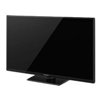
Panasonic TH-32A410H Specifications

General IconGeneral
Screen Size32 inches
Display TypeLED
HDMI Ports2
USB Ports1
Smart TVNo
Aspect Ratio16:9
Resolution1366 x 768 pixels
Display ResolutionHD Ready

Summary

Safety Precautions

Leakage Current Cold Check

Procedure to measure leakage current when the unit is unplugged and cold.

Leakage Current Hot Check

Procedure to measure leakage current when the unit is plugged in and hot.

Warning

Prevention of Electrostatic Discharge (ESD)

Techniques to prevent component damage from static electricity.

Service Mode

How to enter into Service Mode

Step-by-step instructions to access the TV's service mode.

Troubleshooting Guide

Power LED Blinking timing chart

Method of detecting SOS

LCD Panel test mode

No Power

Disassembly and Assembly Instructions

LCD Panel Fixing & Handling Method

Critical procedures for safely installing and handling the delicate LCD panel.

Measurements and Adjustments

Voltage chart of A-board

Specified voltage measurements for various test points on the A-board.

Voltage chart of P-board

Specified voltage measurements for various test points on the P-board.

Schematic Diagram

A-Board (1/14)

Schematic diagram part 1 for the A-board, detailing IIC bus and MTK connections.

A-Board (2/14)

Schematic diagram part 2 for the A-board, covering HDMI and Audio AMP.

A-Board (3/14)

Schematic diagram part 3 for the A-board, detailing AV connections and YPbPr.

A-Board (4/14)

Schematic diagram part 4 for the A-board, focusing on the LVDS interface.

A-Board (5/14)

Schematic diagram part 5 for the A-board, showing SOS and Analog ASIC circuits.

A-Board (6/14)

Schematic diagram part 6 for the A-board, covering terminal connections.

A-Board (7/14)

Schematic diagram part 7 for the A-board, detailing power supply circuits.

A-Board (8/14)

Schematic diagram part 8 for the A-board, covering SPI and E2PROM.

A-Board (9/14)

Schematic diagram part 9 for the A-board, showing USB interface details.

A-Board (10/14)

Schematic diagram part 10 for the A-board, illustrating common power supply circuits.

Printed Circuit Board

Related product manuals