EasyManua.ls Logo

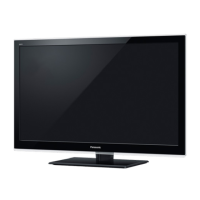
Panasonic TH-L42E5A

Panasonic TH-L42E5A
70 pages
To Next Page IconTo Next Page
Loading...
© Panasonic Corporation 2012. Unauthorized
copying and distribution is a violation of law.
ORDER NO. MTV1204026CE
LCD TV
Model No. TH-L42E5A
Chassis: LA35
Destination: AUSTRALIA
TABLE OF CONTENTS
PAGE PAGE
1 Safety Precautions----------------------------------------------- 3
1.1. General Guidelines---------------------------------------- 3
1.1.1. Leakage Current Cold Check---------------------- 3
1.1.2. Leakage Current Hot Check (See Figure
1.) --------------------------------------------------------- 3
2 Warning -------------------------------------------------------------- 4
2.1. Prevention of Electrostatic Discharge (ESD)
to Electrostatically Sensitive (ES) Devices---------- 4
2.2. About lead free solder (PbF)---------------------------- 5
3 Service Navigation ----------------------------------------------- 6
3.1. Service Hint ------------------------------------------------- 6
4 Specifications ----------------------------------------------------- 7
5 Service Mode ------------------------------------------------------ 8
5.1. How to enter into Service Mode ----------------------- 8
5.1.1. Contents of adjustment mode --------------------- 8
5.1.2. How to exit---------------------------------------------- 8
5.2. SRV-TOOL -------------------------------------------------- 9
5.2.1. How to access ----------------------------------------- 9
5.2.2. Display of SOS History ------------------------------ 9
5.2.3. POWER ON TIME/COUNT ------------------------ 9
5.2.4. Exit --------------------------------------------------------9
5.2.5. Self Check Mode ------------------------------------ 10
5.2.6. Hotel Mode Adjustment---------------------------- 10
5.2.7. Hotel Mode-------------------------------------------- 10
6 Troubleshooting Guide --------------------------------------- 11
6.1. Check of the IIC bus lines------------------------------ 11
6.1.1. How to access --------------------------------------- 11
6.1.2. Exit ------------------------------------------------------ 11
6.1.3. Screen display --------------------------------------- 11
6.2. Power LED Blinking timing chart --------------------- 12
6.3. No Power--------------------------------------------------- 12
7 Disassembly and Assembly Instructions--------------- 13
7.1. Control Button Fixing------------------------------------ 13
7.2. Speaker Bracket & Metal Bottom -------------------- 14
7.3. LCD Panel Assembly ----------------------------------- 15
7.4. LCD Panel Fixing & Handling Method -------------- 16
7.5. LED Panel and Bracket Assembly------------------- 17
7.6. Screw Fixing----------------------------------------------- 18
7.7. Bracket Assembly---------------------------------------- 19
7.8. LVDS FFC 1 ----------------------------------------------- 21

Table of Contents

Question and Answer IconNeed help?

Do you have a question about the Panasonic TH-L42E5A and is the answer not in the manual?

Panasonic TH-L42E5A Specifications

General IconGeneral
BrandPanasonic
ModelTH-L42E5A
CategoryLCD TV
LanguageEnglish

Summary

Safety Precautions

General Guidelines

General advice for safe and correct service procedures.

Leakage Current Cold Check

Procedure to check leakage current with the unit unplugged.

Leakage Current Hot Check

Procedure to check leakage current with the unit powered on.

Warning

Prevention of Electrostatic Discharge (ESD)

Techniques to prevent damage from static electricity to sensitive components.

About lead free solder (PbF)

Information and precautions for using lead-free solder during repairs.

Service Navigation

Service Hint

Provides an overview of the main circuit boards and their functions.

Service Mode

How to enter into Service Mode

Instructions for accessing the service mode using buttons on the unit or remote.

Contents of adjustment mode

Lists adjustable parameters within the service mode with sample data.

How to exit

Method to exit the service mode by powering off the unit.

SRV-TOOL

Accessing and using the SRV-TOOL function within service mode.

Self Check Mode

Instructions to enter and exit the self-check diagnostic mode.

Hotel Mode Adjustment

Steps to enter and adjust settings for hotel mode functionality.

Hotel Mode

Details the purpose and settings available in hotel mode for restricting functions.

Troubleshooting Guide

Check of the IIC bus lines

How to access and interpret IIC bus line checks for troubleshooting.

Power LED Blinking timing chart

Table correlating Power LED blink counts to specific fault conditions.

No Power

Troubleshooting flowchart for diagnosing "No Power" issues based on LED status.

Disassembly and Assembly Instructions

Control Button Fixing

Instructions for securing the control buttons and associated components.

Speaker Bracket & Metal Bottom

Steps for assembling speaker brackets and the metal bottom part.

LCD Panel Assembly

Procedures for assembling the LCD panel, including mounting and alignment.

LCD Panel Fixing & Handling Method

Precautions and steps for safely fixing and handling the LCD panel.

LED Panel and Bracket Assembly

Instructions for assembling the LED panel and its associated brackets.

Screw Fixing

Details on the types and locations of screws used for assembly.

Bracket Assembly

Steps for assembling various brackets within the unit.

Barrier and Metal CH Frame Assembly

Instructions for attaching the barrier and metal chassis frame.

LVDS FFC 1

Procedure for fixing the first LVDS flexible flat cable.

LVDS FFC 2

Procedure for fixing the second LVDS flexible flat cable.

Shading Sheet Sticking

Method for applying shading sheets to specific areas of the chassis.

Shading Plate Sticking

Instructions for applying shading plates and tape.

Bottom Cover Fixing

Steps for attaching the bottom cover and related components.

Back Cover Assembly

Procedure for assembling the back cover of the unit.

Measurements and Adjustments

Voltage chart of A-board

Table listing test points and specified voltages for the A-board.

Voltage chart of P-board

Table listing test points and specified voltages for the P-board.

Block Diagram

Main Block Diagram

Overall block diagram showing major functional units and their interconnections.

Detailed Block Diagram (12)

Detailed schematic of power and main board connections (part 1).

Detailed Block Diagram (22)

Detailed schematic of main board and peripheral connections (part 2).

Wiring Connection Diagram

Wire Dressing

Guidelines and diagrams for routing wires and cables within the unit.

Schematic Diagram

Schematic Diagram Notes

Explains symbols, units, and measurement conditions used in schematics.

A-Board (117) Schematic Diagram

Schematic details for A-Board, focusing on IIC Net.

A-Board (217) Schematic Diagram

Schematic details for A-Board, covering HDMI and Audio-AMP.

A-Board (317) Schematic Diagram

Schematic details for A-Board, related to AVSW-Connection.

A-Board (417) Schematic Diagram

Schematic details for A-Board, covering Initial SETUP and STM Port.

A-Board (517) Schematic Diagram

Schematic details for A-Board, focusing on CI and B-CAS interfaces.

A-Board (617) Schematic Diagram

Schematic details for A-Board, covering LVDS-IF/T-CON and PWM Control.

A-Board (717) Schematic Diagram

Schematic details for A-Board, related to POWER-Model.

A-Board (817) Schematic Diagram

Schematic details for A-Board, covering SET and RS-232C.

A-Board (917) Schematic Diagram

Schematic details for A-Board, common components like NAND, EEPROM, JTAG.

A-Board (1017) Schematic Diagram

Schematic details for A-Board, covering LAN, USB, and SD interfaces.

A-Board (1117) Schematic Diagram

Schematic details for A-Board, related to POWER-Peaks.

A-Board (1217) Schematic Diagram

Schematic details for A-Board, covering LOCK/PEAKS connections.

A-Board (1317) Schematic Diagram

Schematic details for A-Board, related to LOCK-PEAKS-POWER.

A-Board (1417) Schematic Diagram

Schematic details for A-Board, related to LOCK-PEAKS-DCDC.

A-Board (1517) Schematic Diagram

Schematic details for A-Board, related to LOCK-DDR3.

A-Board (1717) Schematic Diagram

Schematic details for A-Board, related to TUNER.

GK-Board Schematic Diagram

Schematic diagram for the GK-Board.

K-Board Schematic Diagram

Schematic diagram for the K-Board.

P-Board Schematic Diagram

Schematic diagram for the P-Board.

Printed Circuit Board

A-BOARD

Component layout and location reference for the A-board.

K-BOARD

Component layout and location reference for the K-board.

P-BOARD

Component layout and location reference for the P-board.

Exploded View and Replacement Parts List

Exploded View and Mechanical Replacement Parts List

List of mechanical parts with their corresponding exploded view references.

Electrical Replacement Parts List

Comprehensive list of electrical components and their part numbers.

Replacement Parts List Notes

Notes and abbreviations used in the replacement parts lists.

Related product manuals