EasyManua.ls Logo

Panasonic TX-21AP1 - User Manual

Panasonic TX-21AP1
6 pages
Print Icon
To Next Page IconTo Next Page
Loading...
Colour Television
TX-21AP1
Z8T Chassis
SPECIFICATIONS
Power Source: 220-240V a.c., 50Hz
Power Consumption: 52W
Stand-by Power
Consumption: 0,9W
Aerial Impedance: 75 unbalanced, Coaxial Type
Receiving System: PAL I, PAL-525/60
M.NTSC (AV only)
NTSC (AV only)
Receiving Channels: UHF E21-E68
Intermediate Frequency:
Video/Audio
Video 39,5MHz
Audio 33,5MHz
32,95MHz (NICAM)
Colour 35,07MHz
Terminals:
AV1 IN Video (21 pin) 1V p-p 75
Audio (21 pin) 500mV rms 10k
RGB (21 pin) 0,7V p-p 75
AV1 OUT Video (21 pin) 1V p-p 75
Audio (21 pin) 500mV rms 1k
AV FRONT Audio (RCAx2) 500mV rms 10k
Video (RCAx1) 1V p-p 75
High Voltage: 27kV ± 1kV
Picture Tube: A51ERF135X71 51cm
Audio Output: 2 x 5W RMS, 2 x 10W MPO
8 Impedance
Headphones: 8 Impedance
Accessories
supplied : Remote Control
2 x R6 (UM3) Batteries
Dimensions:
Height: 476mm
Width: 524mm
Depth: 473mm
Net weight: 22kg
Specifications are subject to change without notice.
Weights and dimensions shown are approximate.
NOTE: This Service Manual should be used in conjunction with
the Z8 Technical guide.
ORDER No. 02-SM-002
Panasonic CS ( U.K. ) Ltd.
WILLOUGHBY ROAD,
BRACKNELL,
BERKS.,
RG12 8FT.
Question and Answer IconNeed help?

Do you have a question about the Panasonic TX-21AP1 and is the answer not in the manual?

Overview

This document describes the Panasonic TX-21AP1 Colour Television, which utilizes the Z8T Chassis. It provides detailed specifications, block diagrams for video, stereo audio, power supply, and deflection, as well as a Y-board schematic.

Function Description

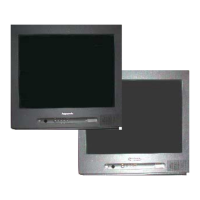
The Panasonic TX-21AP1 is a colour television designed for receiving and displaying broadcast television signals and external audio/video sources. It incorporates a multi-standard sound processor and a Universal One-Chip (UOC) IC for integrated video and control functions. The television supports various video and audio input/output options, including a 21-pin SCART connector (AV1) and front AV inputs. It features a conventional Cathode Ray Tube (CRT) display.

The television's core functionality is managed by the IC601 UOC, which handles video processing, system control, and communication with other components. The IC2001 Multi-Standard Sound Processor manages audio decoding and processing for various broadcast standards. Power management is handled by a dedicated power supply circuit, which provides regulated voltages to all internal components and includes standby functionality. Deflection circuits, including the T552 FBT (Flyback Transformer) and IC451 Vertical Output IC, control the electron beam to create the image on the CRT.

Important Technical Specifications

Power:

  • Power Source: 220-240V a.c., 50Hz
  • Power Consumption: 52W
  • Stand-by Power Consumption: 0.9W
  • High Voltage: 27kV ± 1kV

Display:

  • Picture Tube: A51ERF135X71 (51cm)

Signal Reception:

  • Aerial Impedance: 75Ω unbalanced, Coaxial Type
  • Receiving System: PAL I, PAL-525/60, M.NTSC (AV only), NTSC (AV only)
  • Receiving Channels: UHF E21-E68
  • Intermediate Frequency:
    • Video/Audio: 39.5MHz
    • Video: 33.5MHz
    • Audio: 32.95MHz (NICAM), 35.07MHz

Audio:

  • Audio Output: 2 x 5W RMS, 2 x 10W MPO (8Ω Impedance)
  • Headphones: 8Ω Impedance

Terminals:

  • AV1 IN (21-pin SCART):
    • Video: 1V p-p 75Ω
    • Audio: 500mV rms 10kΩ
    • RGB: 0.7V p-p 75Ω
  • AV1 OUT (21-pin SCART):
    • Video: 1V p-p 75Ω
    • Audio: 500mV rms 1kΩ
  • AV FRONT:
    • Audio (RCAx2): 500mV rms 10kΩ
    • Video (RCAx1): 1V p-p 75Ω

Physical:

  • Dimensions:
    • Height: 476mm
    • Width: 524mm
    • Depth: 473mm
  • Net weight: 22kg

Note: Specifications are subject to change without notice. Weights and dimensions shown are approximate.

Usage Features

The TX-21AP1 television offers a range of features for user convenience and connectivity:

  • Multi-Standard Compatibility: Supports various broadcast standards (PAL I, PAL-525/60, M.NTSC, NTSC), allowing it to be used in different regions or with diverse video sources.
  • Multiple AV Inputs: Includes a versatile 21-pin SCART connector (AV1) for connecting a wide array of external devices such as VCRs, DVD players, and set-top boxes, supporting composite video, audio, and RGB signals. Front AV inputs (RCA for audio, RCA for video) provide easy access for temporary connections like camcorders or gaming consoles.
  • Audio Output Options: Features stereo audio output for connecting to external amplification systems and a headphone jack for private listening.
  • Remote Control: Comes with a remote control and two R6 (UM3) batteries for convenient operation from a distance.
  • Standby Mode: Low power consumption in standby mode (0.9W) contributes to energy efficiency.
  • System Control: The IC601 UOC integrates system control functions, likely including channel tuning, volume control, on-screen display (OSD), and input selection.
  • Sound Processing: The IC2001 Multi-Standard Sound Processor ensures high-quality audio reproduction across different broadcast standards, including NICAM support.

Maintenance Features

This service manual provides essential information for the maintenance and repair of the TX-21AP1 television:

  • Block Diagrams: Comprehensive block diagrams for video & stereo audio, power supply & deflection, and control systems facilitate troubleshooting by illustrating the signal flow and interconnections between major components.
  • Component Identification: Key integrated circuits (ICs) such as IC601 (UOC), IC2001 (Multi-Standard Sound Processor), IC251 (Audio Output IC), IC351 (Y-Board IC), and IC451 (Vertical Output IC) are clearly identified, aiding in component-level repair.
  • Voltage References: The power supply block diagram indicates various voltage lines (e.g., 33V, 5V, 8V, +190V, 27kV high voltage), which are crucial for diagnosing power-related issues.
  • Signal Paths: The diagrams show signal paths for IF, video, audio, RGB, and control signals, enabling technicians to trace faults effectively.
  • Test Points: Although not explicitly labeled as "test points," the diagrams indicate various inputs and outputs of ICs and modules (e.g., IF1, IF2, VIDEO OUT, AUDIO OUT, PROT, AGC), which serve as critical points for measurement during diagnostics.
  • Y-Board Schematic: A detailed schematic of the Y-Board (TNP8EY015) is provided, showing the CRT driver circuitry (IC351 TDA6107Q) and associated components, which is vital for troubleshooting display-related problems.
  • Fuse and Switch Locations: Fuses (e.g., F801, F851, F852, F853) and switches (e.g., S802) are indicated, allowing for quick checks of power protection and control elements.
  • Inter-Board Connections: Connectors between different boards (e.g., E2, E3, E4, E5, E6, E7, E8, Y2, Y3) are shown, which is important for identifying connection issues or replacing modular components.
  • Technical Guide Reference: The note "This Service Manual should be used in conjunction with the Z8 Technical guide" indicates that further detailed technical information, likely including circuit diagrams, component layouts, and adjustment procedures, is available in a supplementary document for comprehensive maintenance.

Panasonic TX-21AP1 Specifications

General IconGeneral
BrandPanasonic
ModelTX-21AP1
CategoryTV
LanguageEnglish

Related product manuals