32
Connectors
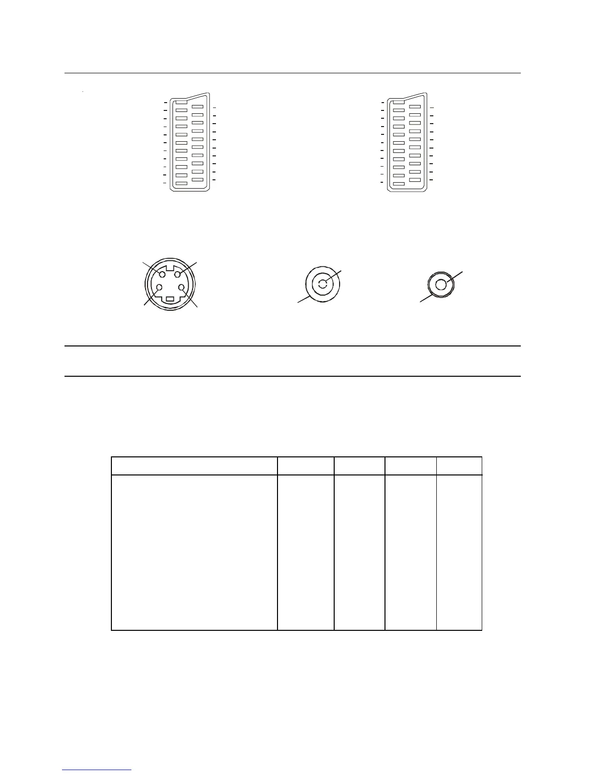
AV1 / AV4 Scart Socket AV2 Scart Socket (S – Video, Q-Link)
Use AV1 or AV4 for YP
R
P
B
(YUV) inputs. AV2 – Pins 15 and 20 are dependent on
AV2 – VHS / VIDEO switching
S-Video 4 Pin socket RF Socket RCA Socket
Connecting Equipment to the TV - Rear Panel
Most DVD players and Set Top Boxes have both a composite video and YP
B
P
R
(YUV) video outputs. The YP
B
P
R
system produces a better picture and we recommend that you use this output. If your DVD player or STB does
not have YP
B
P
R
output, use the Video Out terminal. The supplied Scart to 6 RCA cable can be connected to
either output. If your DVD player or STB has different type connectors please refer to your instruction book for
details.
Device AV1 AV2* AV3 AV4
DVD Player (Component video) Yes No No Yes*
DVD Player (S-Video) No Yes Yes Yes
DVD Player (Composite video) Yes Yes Yes Yes
STB (Component video) Yes No No Yes*
STB (S-Video) No Yes Yes Yes
STB (Composite video) Yes Yes Yes Yes
VCR (S-Video) No Yes Yes Yes
VCR (Standard) Yes Yes Yes Yes
VCR (Q-Link) No Yes No No
Camcorder (S-Video) No Yes Yes Yes
Camcorder (Composite video) Yes Yes Yes Yes
Games Console (RGB) * Yes No No Yes
Computer (RGB) * Yes No No Yes
* Notes:
1. The AV2 Scart socket can output selectable Audio/Video signals to other equipment. Refer to AV2 Out
set up on page 15.
2. AV1 and AV4 can supply Monitor out signals using a Scart cable or a Scart adaptor switched to “OUT”
3. You can connect YP
B
P
R
video to AV4 using the RCA sockets only, the audio for AV4 can only be
connected through the Scart socket.
4. Do not connect a computer or games console with TTL output (5V) to this television.
Socket earth 21
CVBS out (video) 19
CVBS earth 17
P In (or RGB-Red) 15
Earth 13
Y In (or RBG-Green) 11
Earth 9
P In (or RGB-Blue) 7
Earth 5
Audio out ( L ) 3
Audio out ( R ) 1
R
R
20 CVBS in (video)
18 RGB Status earth
16 RGB Status
14 Earth
12 - -
10 - -
8 Status
6 Audio in ( L )
4 Audio earth
2 Audio in ( R )
CVBS
Socket earth 21
CVBS out



 To Next Page