EasyManua.ls Logo

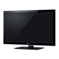
Panasonic TX-L32E30B - User Manual

Panasonic TX-L32E30B
70 pages
To Next Page IconTo Next Page
Loading...
Service Manual
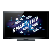
LCD Television
TX-L32E30B
TX-L32E30Y
TX-L37E30B
TX-L37E30Y
LA18 Chassis
Specifications
(Information in brackets [ ] refers to model 32”)
Power Source: 220-240V AC, 50 / 60Hz
Rated Power Consumption: 85W [72W]
Stand-by Power Consumption: 0.3W (Without monitor out recording)
14W (With monitor out recording)
Aerial Impedance: 75 unbalanced, Coaxial Type
Receiving System: E30B ( UK )
PAL-I
PAL-525/60 (AV only)
DVB-T/T2 Digital terrestrial services via UHF aerial input (MPEG2 and MPEG4-AVC
(H.264))
M.NTSC (AV only)
NTSC (AV only)
E30B ( Ireland )
PAL-I
PAL-525/60 (AV only)
M.NTSC (AV only)
NTSC (AV only)
DVB-T Digital terrestrial services (MPEG2 and MPEG4-AVC
(H.264))
E30Y
PAL-I/H, B/G, D/K
SECAM B/G, D/K, L/L’
PAL-525/60 (AV only)
M.NTSC (AV only)
NTSC (AV only)
DVB-T/T2 (Digital Terrestrial Services (MPEG2 and MPEG4-AVC
(H.264))
DVB-C (Digital cable services (MPEG2 and MPEG4-AVC
(H.264))
© Panasonic Corporation 2011.
Unauthorized copying
and
distribution is a violation of law.
ORDER No. PCZ1102006CE
Question and Answer IconNeed help?

Do you have a question about the Panasonic TX-L32E30B and is the answer not in the manual?

Panasonic TX-L32E30B Specifications

General IconGeneral
Screen Size32 inches
Display TechnologyLCD
Panel TypeIPS
BacklightLED
HDMI Ports4
USB Ports2
Wi-FiYes
EthernetYes
Smart TVYes
3DNo
Refresh Rate100 Hz
Aspect Ratio16:9
Energy Efficiency ClassA
Resolution1920 x 1080 (Full HD)
Weight11.5 kg

Summary

Product Specifications

Important Safety Precautions

General Service Guidelines

Essential guidelines for safe and effective TV servicing.

Touch Current Measurement

Procedure for measuring touch currents for electrical safety compliance.

Electrostatic Discharge (ESD) Prevention

ESD Handling Procedures

Guidelines for handling sensitive electronic components to prevent ESD damage.

Lead-Free Solder (PbF) Information

Suggested Pb-Free Solder Types

Recommendations for suitable lead-free solder types for repair.

Service Troubleshooting Hints

Backcover Removal Procedure

Step-by-step instructions for safely removing the television's backcover.

Chassis Board Layout and Wiring Guide

Lead Wiring Identification

Identification and routing of internal wiring harnesses and connectors.

Technical Details and Key Features

Key Feature Specification (CI Plus, DTCP-IP)

Details on security keys for various digital content protection features.

Model Feature Key Mapping

Table correlating specific models with supported feature key functionalities.

Setting Inspection and Voltage Checks

Voltage Confirmation Table

Test points and expected voltage values for A and P boards for diagnostics.

TV Self-Check Diagnostics

Self-Check Procedure and Results

How to perform a self-check and interpret the results for troubleshooting.

Power LED Blinking Error Codes

LED Blinking Timing Chart

Chart detailing power LED blink patterns indicating specific faults.

Service Mode Operations

Entering Service Mode

Instructions to access the service menu via remote control and TV buttons.

Service Mode Navigation and Adjustments

Key Commands for Service Mode

Explanation of remote control buttons for service mode navigation and value adjustment.

Service Tool Mode Access and Information

How to Access Service Tool Mode

Steps to enter the Service Tool Mode for diagnostic information.

Hotel Mode Setup and Configuration

Hotel Mode Access Command

Command sequence to enter the hotel mode setup menu for restrictions.

SD Card Data Copy Procedures

Data Copy for Board Replacement

Procedure for copying data for A-board replacement using an SD card.

Data Copy for Hotel Installation

Procedure for copying data for multiple hotel installations using an SD card.

TV to SD Card Data Transfer

Copying TV Data to SD Card

Steps to copy TV settings and data to an SD card.

SD Card to TV Data Transfer

Copying SD Card Data to TV

Steps to restore TV settings and data from an SD card.

Option Bytes Configuration Guide

OPTION1 Byte Settings Description

Description of OPTION1 byte settings and their functions.

OPTION2 Byte Settings Description

Description of OPTION2 byte settings and their functions.

OPTION3 Byte Settings Description

Description of OPTION3 byte settings and their functions.

OPTION4 Byte Settings Description

Description of OPTION4 byte settings and their functions.

Adjustment Procedures and Methods

Sub-Contrast and White Balance Adjustment

Procedures for adjusting sub-contrast and white balance using service tools.

Wiring Diagram Overview

A-BOARD Wiring Connections

Diagram illustrating connections and pinouts for the A-BOARD.

System Block Diagram (Part 1)

Major Functional Blocks Overview (1;2)

High-level overview of major functional blocks and their interconnections.

System Block Diagram (Part 2)

Major Functional Blocks Overview (2;2)

Continuation of the high-level overview of functional blocks.

Component Location Guide

Exploded View Parts Identification

Visual guide to the location of major internal and external components.

Replacement Parts List

Common and Miscellaneous Parts

List of common parts, exploded view components, and miscellaneous items.

Schematic Diagram Conventions

Symbols, Units, and Measurement Notes

Explanation of symbols, units, and measurement notes used in schematics.

A-BOARD Conductor View (Top)

A-BOARD Conductor Layout (Top View)

Top-side trace layout and component placement for the A-BOARD.

A-BOARD Conductor View (Bottom)

A-BOARD Conductor Layout (Bottom View)

Bottom-side trace layout and component placement for the A-BOARD.

P-BOARD Conductor View (Top)

P-BOARD Conductor Layout (Bottom View)

Bottom-side trace layout and component placement for the P-BOARD.

LD-BOARD Conductor View (Top)

KA-BOARD Conductor View (Top)

Top-side component layout for the KA-BOARD.

Related product manuals