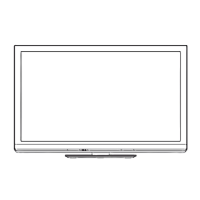
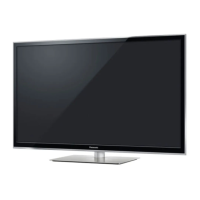
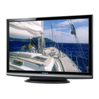
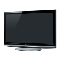
Do you have a question about the Panasonic TX-P42G30E and is the answer not in the manual?
General guidelines for safe repair and servicing procedures.
Procedure to measure touch currents to ensure safety.
Techniques to prevent damage from static electricity to sensitive components.
Information and precautions regarding the use of lead-free solder.
Identifies components and their locations on the Printed Circuit Boards.
Lists supported input signals for component and HDMI connections.
Details about the security keys required for digital content protection.
Information on recording TV programs using a USB HDD.
Instructions on accessing and navigating the service mode.
Lists adjustable parameters and their sample data within the service mode.
Settings for reversing the picture display (left/right or up/down).
Accessing and using the service tool mode for diagnostics.
Configuration options for hotel usage, restricting functions.
Procedure for copying and restoring data using an SD card.
Steps to copy TV settings and data to an SD card.
Steps to restore TV settings and data from an SD card.
Procedure to check IIC bus communication for diagnostics.
Interpreting power LED blinking patterns to diagnose issues.
Troubleshooting steps for situations where the TV does not power on.
Troubleshooting steps for no picture display.
Identifying potential PCB causes for localized screen display issues.
Instructions for removing the rear casing of the TV.
Procedure for safely removing the AC power inlet.
Steps to remove the Power Supply Board (P-Board).
Instructions for removing the side terminal cover.
Steps to remove the TV tuner module.
Procedure for removing the Main AV Input/Processing Board (A-Board).
Procedure for removing the SN-Board.
Steps to remove the SS-Board.
Instructions for removing the TV's stand bracket.
Steps to remove the C1-Board.
Procedure for removing the C2-Board.
Instructions for removing chassis support metals and M8 nuts.
Cautionary notes and initial steps for replacing the plasma panel.
Procedure for selecting the Vsus setting (LOW or HIGH).
Steps for adjusting sub-contrast for RF and AV systems.
Method for adjusting white balance according to PEAKS EEPROM version.
Overall block diagram of the TV's main functional units.
Detailed block diagram section 1 of 4.
Detailed block diagram section 2 of 4.
Detailed block diagram section 3 of 4.
Detailed block diagram section 4 of 4.
Important cautions regarding cable assembly and connection.
Wiring diagram for speaker connections.
Wiring diagram showing connections for various boards and components.
Wiring diagram illustrating connector and board connections.
Wiring diagram for power board connections.
| Screen Size | 42 inches |
|---|---|
| Display Type | Plasma |
| HDMI Ports | 4 |
| Wi-Fi | Yes |
| Ethernet | Yes |
| Audio Output | 20 W |
| Aspect Ratio | 16:9 |
| Tuner | DVB-T/C/S2 |
| 3D | Yes |
| Smart TV | Yes |
| Refresh Rate | 600 Hz |
| Resolution | 1920 x 1080 |
| Contrast Ratio | 5, 000, 000:1 (Dynamic) |
