3
English
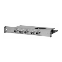
Terminals
5 4 3 2 1
1 SDI 1 IN: SDI input terminal
TerminaltoinputSDIsignals(12G-SDI/3G-SDI/
HD-SDI).
2 SDI OUT: SDI output terminal
TerminaltooutputSDIsignals(12G-SDI/3G-SDI/
HD-SDI)astheyarethathavebeeninputtotheSDI
1INterminal.
3 SDI 2 IN: SDI input terminal
TerminaltoinputSDIsignals(3G-SDI/HD-SDI).
4 SDI 3 IN: SDI input terminal
TerminaltoinputSDIsignals(3G-SDI/HD-SDI).
5 SDI 4 IN: SDI input terminal
TerminaltoinputSDIsignals(3G-SDI/HD-SDI).
Note
●
SDI2IN,SDI3INandSDI4INterminalsareused
onlyforQuadLinkconnection.
●
Usea5C-FBcable,L-5.5CUHDcableorequivalent
toconnecttotheSDIterminal.
●
Whenperformingtheactive-throughoutputwhilethe
LCDdisplayisinstandbymode,set[SLOTsettings]-
[SLOTstandby]ofthedisplayto[On].
●
IfCRCCerror(page6)occurs,checkthecable
touse.
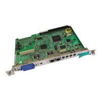
Replacing the
terminal board
The replacement instruction below is based on the
flat panel display SQ1 series as an example.
Forattachingorremovingthisproducttoorfromtheflat
paneldisplayunit,itisrecommendedtoaskaqualified
technicianorsalesdealer.Amalfunctionmayoccurdue
tostaticelectricity,etc.Consultthesalesdealer.
Followthestepsbelow.
Note
●
Besuretoturnoffthedisplayunitandconnected
devices,removethepowerplugfromthesocket,and
disconnectthecablesfromthedisplay.
●
Whenattaching/removingtheterminalboard,donot
allowthemetaltodamagethebackcoverordisplay
label.
1
Remove the 2 screws, and then remove the slot
cover or terminal board from the display unit.
Toremovetheterminalboard,holdthehandleof
theterminalboardandpullitoutslowlyinthearrow
direction.
2
Insert the terminal board to the main unit slot,
and tighten the 2 screws.
Fixtheterminalboardwiththe2screwsremovedin
step1.
●
Tighteningtorqueguideline:0.5N·morless
Note
●
Whenreplacinganotherterminalboardwiththis
product,thecustomershallkeepthereplaced
terminalboardforfuturerepairorservicing.
 Loading...