EasyManua.ls Logo

Panasonic U-36LE1U6 - Diameter for Power Supply System; Wiring System Diagram

Panasonic U-36LE1U6
48 pages
Print Icon
To Next Page IconTo Next Page
To Previous Page IconTo Previous Page
Loading...
* Disconnect switch
(
Field Supply)
*
*
*
*
2
1
WHT
Remote
Controller
Group control:
BLK
2
1
2
1
WHT
Remote
Controller
B
C
Indoor
unit (No . n)
Indoor
unit (No. 1)
Indoor
unit (No. 2)
Indoor
unit (No. 3)
A
Ground
L1
L2
L1
L2
L1
L2
L1
L2
BLK
2
1
Power supply
208 / 230V, 60Hz, 1-PH
Power supply
208 / 230V, 60Hz, 1-PH
Power supply
208 / 230V, 60Hz, 1-PH
Power supply
208 / 230V, 60Hz, 1-PH
Ground
Ground
Ground
A
B
A
U2
U1
L2
L1
R2
R1
U2
U1
L2
L1
R2
R1
U2
U1
L2
L1
R2
R1
U2
U1
L2
L1
ALWAYS COMPLY WITH NATIONAL AND
LOCAL CODE REQUIREMENTS.
*
NOTE:
Disconnect Switch may be needed by the
National/Local code.
K1 Type
2
1
B
1
3
Remote
Controller
CONNECTOR
2P (WHT)
RC
(BLU)
WHT
BLK
WHT
BLK
WHT
BLK
WHT
BLK
*
Outdoor unit
INV unit
L1
L2
Ground
Power supply
208 / 230V, 60Hz, 1-PH
A
2
1
L2
L1
L1 1 2L2
Power
supply
Outdoor Unit
5P terminal board
4-3.Wiring System Diagram
NOTE
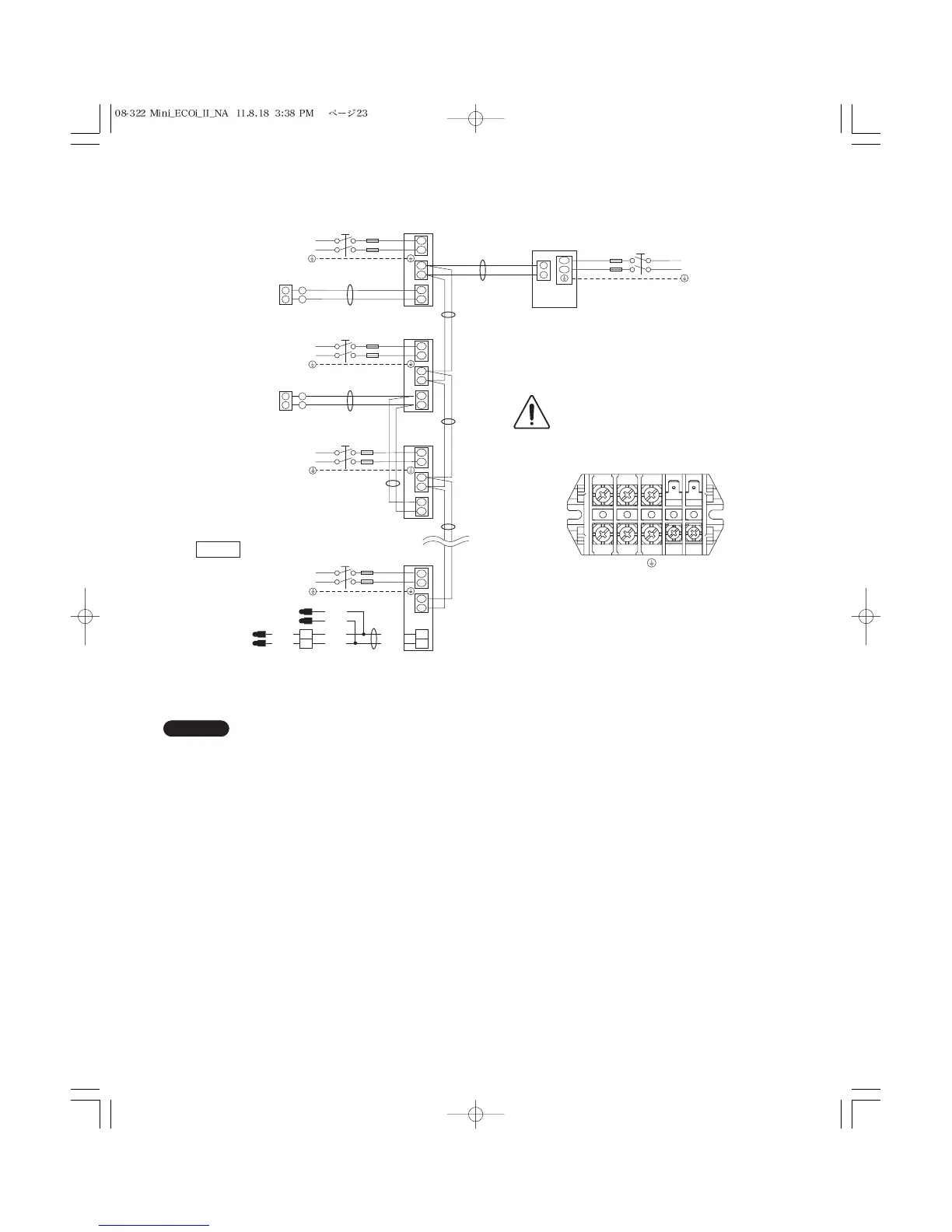
(1) Refer to Section 4-2. “Recommended Wire Length and
Wire Diameter for Power Supply System” for the expla-
nation of “A, “B, and “C, in the above diagram.
(2) The basic connection diagram of the indoor unit shows
the 6P terminal board, so the terminal boards in your
equipment may differ from the diagram.
(3) Refrigerant Circuit (R.C.) address should be set before
turning the power on.
(4) Regarding the R.C. address setting, refer to Section 7-4.
“Auto Address Setting”. Address setting can be executed
by remote controller automatically.
23

Table of Contents

Other manuals for Panasonic U-36LE1U6

Related product manuals