1-1 1-2
2-1 2-2 2-7
1-3 1-6
2
7
7
ON
1
2
ON
OFF
Automatic address setting in Heating mode
Automatic address setting in Cooling mode
* When multiple outdoor units exist, remove the socket that
is used to short-circuit the terminal plug (CN33) from all
outdoor unit PCBs except for 1.
Alternativel y , move the sockets to the “OPEN” side .
Leave the socket
that is used to
short-circuit the
terminal plug.
(CN33)
T o other syste m
link wiring
Indoor and outdoor unit power can be turned ON for each system separately.
Case 2
Case 1
Case 3
Make settings as appropriate for the cases listed belo w .
(Refer to the instructions on the following pages.)
Leave the socket
that is used to open
circuit the terminal
plug (CN33).
6
(S004)
1
ON
1
2
ON
OFF
(S003)
(S002)
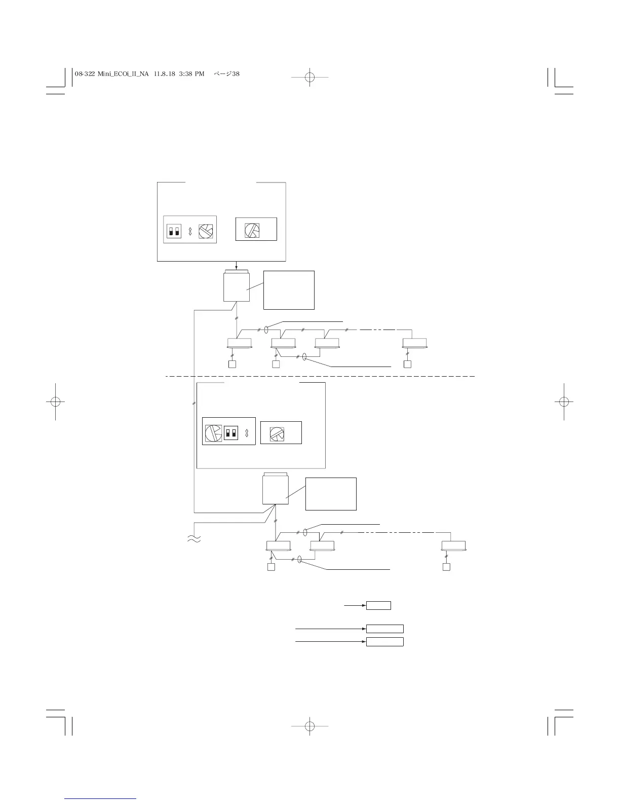
If link wiring is used
No. 1 unit settings
Unit
No. 1
Outdoor unit
system 1
Unit
No. 1
Outdoor unit
Indoor unit
Remote
Controller
Indoor unit
Remote
Controller
Inter-unit control wiring
Inter-unit control wiring
Remote control
communucation wiring
Remote control
communucation wiring
(S004)
(S003) (S002)
No. 2 unit settings
System address
(system 1 setting)
System address
(system 2 setting)
No. of indoor units
(6 units setting)
system 2
Indoor and outdoor unit power cannot be turned ON for each system separately.
No. of indoor units
(7 units setting)