5
5 - 15
3WAY SYSTEM
Trouble Diagnosis
4. 3WAY Alarm Codes
F17 Alarm
Alarm code F17
Alarm meaning Low-pressure sensor trouble
Alarm conditions
(2) Sensor open circuit
Probable cause
(2) PCB malfunction
Check
(1) Sensor short circuit
(1) Sensor malfunction (including connector)
(1) Measure the sensor resistance. Check that the sensor is operating normally.
(2) Use a remote monitor or a PC monitor to check the temperature that is recognized
by the microcomputer.
F31 Alarm
Alarm code F31
Alarm meaning Outdoor unit non-volatile memory (EEPROM) trouble
Alarm conditions
(2) Read values do not match after writing to non-volatile memory is complete.
Probable cause
(1) Non-volatile memory is not present when power initialization occurs.
(1) Memory was not inserted after the PCB was replaced.
(2) The lifetime of the non-volatile memory has been reached.
(3) Non-volatile memory is installed incorrectly (wrong direction, bent pins, etc.).
Check (1) Check the non-volatile memory on the PCB.
Correction
Example
Notes
—
Correction —
—
Example —
—
Notes —
(1) Wiring failure
(2) Operating under extremely high-pressure status (over-loaded operation)
(3) Power source and voltage failure (sudden voltage decrease)
(2) Operating under extremely high-pressure status
(over-loaded operation)
Check open/closed status of the service valve of the outdoor unit.
(3) Check power source and voltage.
H01 Alarm
Alarm code
Alarm meaning
Alarm conditions
Probable cause
Check
Correction
Example
Notes
H01
Compressor 1Currenttrouble
Compresor 1 (INV) primary current detected overcurrent higher than the values (overcurrent) listed
in the table below.
(1) Wiring failure
(2) Operating under extremely high-pressure status (over-loaded operation)
(3) Improving power source and voltage
(1) Wiring failure
—
—
Horsepower of unit
Current (A)
8HP
15.1
10HP
19.8
12HP
21.0
14HP
21.0
16HP
22.5
Failure to open the service valve of the outdoor unit•
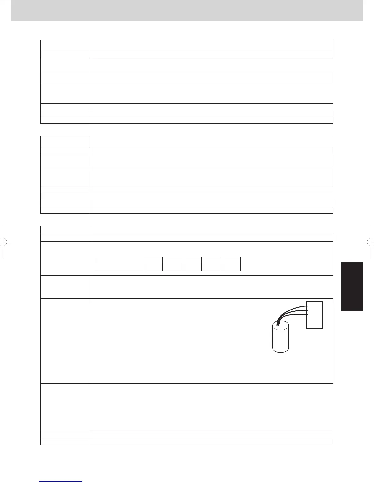
Check whether the connection between "HIC PCB" and " inverter
compressor" is wiring failure.
See the fugure at right.
Difference of characteristics of high-pressure sensor (under-shift)•
Open the service valve of the outdoor unit.•
Correct wiring disconnection and wiring failure.
Replacing high-pressure sensor
When replacing a high-pressure sensor, carry out after refrigerant recovering of the outdoor unit.
•
Connect a gauge to the high-pressure outlet and check for
changes in the value dispalyed by the monitoring software, and for
large deviation of the gauge pressure.
•
Inverter compressor
HIC PCB
U
V
W
5/A9#;'%1K5;56'/A5G