Project Design
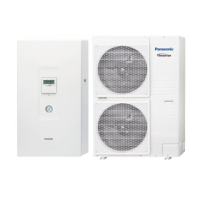
Planning heat source – air
Bi-Bloc system
Fastening the
outdoor unit
2
1
1
3
Minimum distances from the out-
door unit to the neighbouring walls
and objects with representation of
air ow direction. The connection of
the refrigerant piping can occur in
one of four directions (front, rear,
side, down).
The outdoor unit must be installed on a at, level and solid surface.
The weight of the water in addition to the weight of the unit must be
taken into consideration. Four M12 anchor bolts with a pull-out force
greater than 15,000 N are required for fastening.
Minimum requirements for
anchoring the outdoor unit
to the oor or a foundation (left)
or directly to a base plate (right).
* Different for 3 kW and 5 kW
units (see dimensioned drawing)
1
Base
2
Gravel
3
Strip foundation
or base plate
4
Anchor bolt
5
Drainage pipe
All dimensions in mm
≈100
4
800
3
1
5
2
355*
460
420*
620*
200
≥ 300
≥ 60
 Loading...