6. Synchronization Setting (SYNC)
1. Select a sync mode.
VD2: Multiplexed vertical drive, highest priority
LL: Line-Lock, follows the phase of supplied AC power, 2nd priority
EXT (VBS): Composite color video or black-burst sync, 3rd priority
EXT (VS): Composite monochrome video or composite HV sync, 4th priority
INT: Internal sync, lowest priority
Note: Selection is not available when VD2 is added to the camera. Selection from LL and
VBS/VS is available when the respective sync is added.
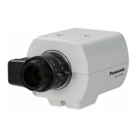
2. Line-Lock Vertical Phase Adjustment (V PHASE)
• Select LL and press SET.
• Prepare a dual-trace oscilloscope and supply it with the video output of the camera to be
adjusted and that of the reference camera.
• Set the oscilloscope to the vertical rate and
expand the V-sync portion.
• Select a proper COARSE phase from 16
steps (22.5 degrees/step) that makes the
two video signals on the oscilloscope the
closest.
• Select a proper FINE phase so that the two
video signals on the oscilloscope come as
close as possible.
Notes:
• Moving the "I" cursor across the +/- end
will shift the FINE range.
• Press L and R simultaneously to reset the V PHASE to the default (0 degree).
• Keep pressing L or R for a second to move the "I" cursor faster if necessary.
• Spike noise if contained in the AC mains may disturb synchronization of LL.
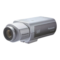
3. VBS Phase Adjustment (H PHASE/ SC)
• Select INT for SYNC.
• Supply a VBS (Composite color video or black-burst) signal to the GEN-LOCK IN termi-
nal.
→ INT will change to EXT (VBS).
• Select EXT (VBS) and press SET.
→ A sub menu displaying H PHASE and SC
(Sub carrier) opens.
<H PHASE Adjustment>
• Prepare a dual-trace oscilloscope and
supply it the video output of the camera
to be adjusted and the VBS.
• Set the oscilloscope to the horizontal rate
and expand the H-sync portion.
• Move the "I" cursor so that phase of the VBS and that of the camera match on the
oscilloscope.
Adjustable range: From zero to – 2.0 microseconds
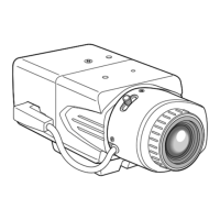
<SC (Sub-carrier) Phase Adjustment>
• Connect the camera to a special effect generator (SEG) and supply the output of the
SEG to a monitor.
• Select a proper COARSE phase from 4 steps (90 degrees/step) while observing the
original scene and the scene on the monitor to make these colors similar.
• Select a proper FINE phase so that these colors match as closely as possible.
• For more accurate adjustment, prepare a vectorscope and supply it with the camera
signal to be adjusted and the output of the SEG as a reference signal. Adjust SC to
match on the vectorscope.
4. VS Phase Adjustment (H PHASE)
• Supply a VS (Composite monochrome video
or composite HV) signal to the GEN-LOCK
IN terminal.
• Adjust the H phase referring to
<H PHASE Adjustment> described above.
7. White Balance Setting (WHITE BAL)
Select a mode for WHITE BAL on the CAMERA SETUP menu. The default is ATW1.
ATW1: Is automatically adaptable to the color temperatures of 2 700K - 6 000K.
ATW2: Is automatically adaptable to the use of sodium lamps (2 000K - 6 000K).
AWC: Is automatically adaptable to the color temperatures of 2 000K -10 000K.
Notes:
• When ATW1 or ATW2 is selected, no further operation is required.
• ATW1 and ATW2 do not appear on the setup menu of the system controller.
• Select AWC in the following cases: the color temperature is out of the 2 000K - 6 000K
range, the scene contains mostly high color temperatures such as blue sky or sunset,
or the scene is dim.
AWC Setting
1 Select AWC and press L.
→ AWC will change to AWC → PUSH SW.
2 Press SET.
→ PUSH SW will be highlighted while the AWC setting is performed.
Note: If the white balance is not set, PUSH SW is being highlighted.
3 Press R.
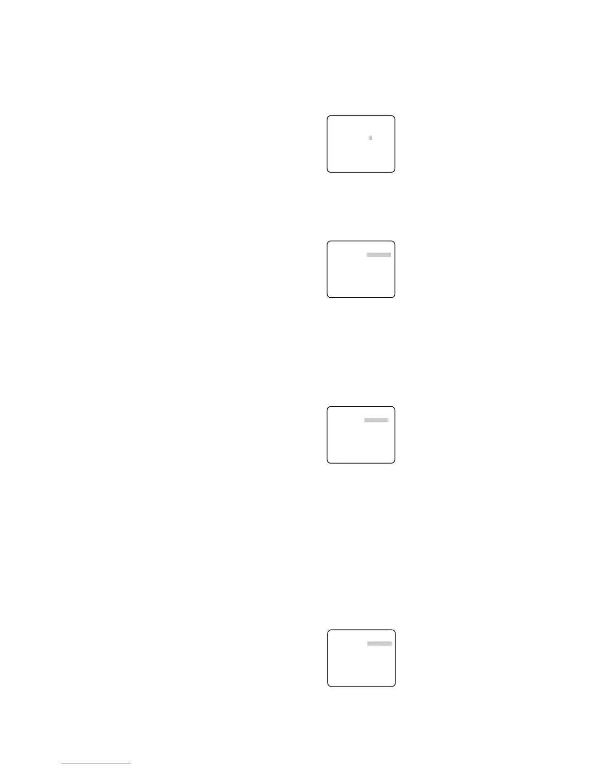
Manual Fine Adjustment
Perform fine adjustment as necessary.
1. Select WHITE BAL and press SET.
→ Fine adjustment menu of ATW or AWC will
open.
2. Adjust finely R (Red) and B (Blue) gain by
moving the "I" cursor.
 Loading...