12072021 7
PANTHER / PREDATOR / APPLICATOR ASSEMBLY PREVENTATIVE MAINTENANCE
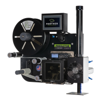
10. Check the location of the applicator home sensor. Remove the M8 power cable from the back of the
sensor, then loosen the jam nut on the applicator home sensor. Turn the applicator home sensor in until it
contacts the applicator rack. Loosen it by a half turn, then tighten the jam nut. Reconnect the M8 power
cable.
OPTIONAL ADJUSTMENT APPLICATOR POSITIONING
Over time, your applicator may move out of position. When servicing your applicator, we encourage you to
check that the applicator head is in the following recommended position. The information on the subsequent
pages picks up immediately following the preventative maintenance steps 1-10 above.
To Adjust the Applicator Assembly:
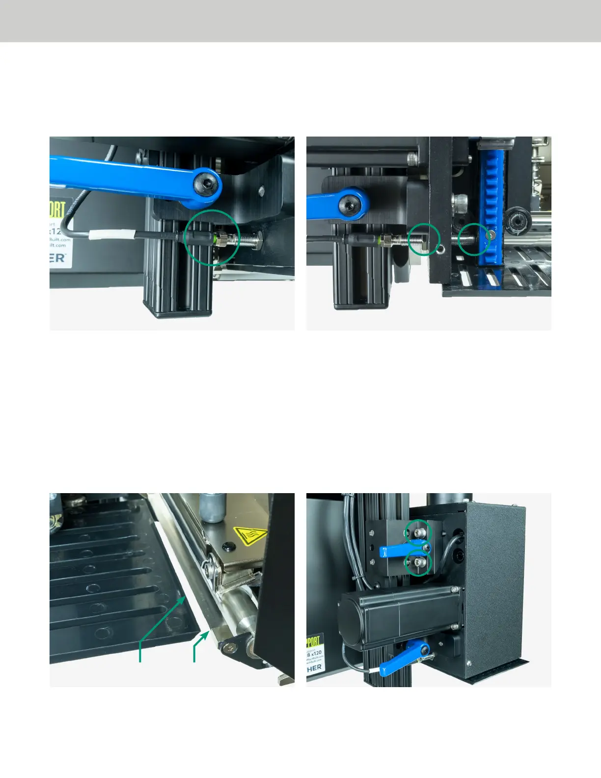
11. The applicator should be positioned so that the tamp head is approximately 1/8” away from the print
engine peel bar. You may adjust the horizontal distance by loosening the two (2) 3/8 - 16 x 2 1/2” mounting
bolts, located adjacent to the rack guide.
Tamp Head Peel Bar
 Loading...