24 LT5052 (ISS 5)
1: Mounting the INSET Fan Housing – Fire sited in cavity
IMPORTANT: Study the enclosed Fan Unit Template carefully before INSTALLATION. The Fan unit must be fitted with
the fan outlet directed downwards (fig. 6).
If installing the appliance into a conventional cavity wall, mark opening as shown in fig. 2 & 3.
Drill a pilot hole through both inner and outer leaf at the required position.
Cut away the plaster and inner leaf of brickwork to this line, exposing the cavity and rear face of the outer wall.
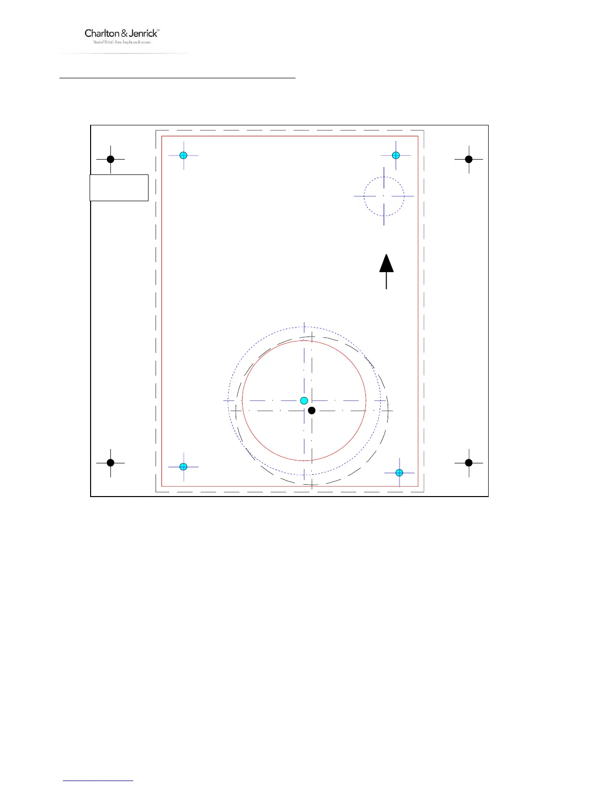
Using the template provided (shown in fig. 4), position the light grey dot in the centre of the large circle over the pilot
hole on the outside brickwork.
Mark the wall following the long broken line, using a grinder cut out the rectangular hole for the fan housing.
The housing will be secured to the wall at the positions shown by the black dots using suitable fixings later.
Secure the fire into the opening, gas supply pipe and electrical cable appropriately routed in accordance with current
regulations (NOTE: fire isolated from electrical supply at this time).
Remove the front cover from the housing and place to one side.
Disconnect the tubes from the pressure switch, making note of which tube fits on which outlet, (‘+’ on pressure switch
to upper venturi outlet, ‘-‘ on pressure switch to lower outlet on venturi). Refer to fig. 6.
SURFACE MOUNT
WIRING HA RNE SS HOLE
35mm
FOR FAN UN IT S ET ON A N EX T ERIOR W A LL.
T HE W IRIN G HAR NES S C AN B E ROUT ED TH ROU GH A 35m m HOLE DRILLE D A T T HE P OS ITION S HOW N.
IT MUS T B E P ROT E CT E D B Y A CONDU IT T O PR EVE NT IT C OMING INT O CONT ACT W IT H T HE FLUE OR FIRE BOX .
FOR FAN UN IT S ET IN T HE E X TE R IO R W AL L.
T HE W IRIN G HAR NES S C AN B E ROUT ED AL ONG S IDE T HE FLU E IF RE QUR ED B UT IT MUS T B E
P ROT ECT ED BY A CON DUIT T O P REV E NT IT COMING INTO CONT ACT W IT H T HE FLU E OR FIR E B OX.
NOTE: SOLID LINE DENOTES THE OUTER PROFILE
OF THE FAN UNIT AND ACTUAL FLUE POSITION.
TO FIT FAN UNIT ON THE SURFACE OF AN
EXTERIOR WALL FOLLOW PROFILE OF THE
THE DOTTED LINE. SECURE TO W ALL
USING SUITABLE FIXINGS.
SURFACE MOUNT
SECURING HOLE
SURFACE MOUNT
SECURING HOLE
SURFACE MOUNT
SECURING HOLE
INSET
SECURING HOLE
INSET
SECURING HOLE
INSET
SECURING HOLE
SURFACE MOUNT
SECURING HOLE
INSET
SECURING HOLE
TO FIT THE FAN UNIT IN THE EXTERIOR
WALL FOLLOW PROFILE OF THE BROKEN
LINE. SECURE TO WALL USING SUITABLE
FIXINGS.
PARAGON 2000 TURBO
FAN UNIT TEMPLATE
THIS TEMPLATE IS TO BE POSITIONED
ON THE OUTSIDE WALL OVER A PILOT
HOLE DRILLED AS DESCRIBED IN THE
INSTRUCTIONS.
(PILOT HOLE POSITION - CENTRE LINE
OF FIRE, 483mm VERTICAL FROM HEARTH LEVEL.)
RE FER T O INST ALLAT IO N I NST RUCT IONS BEF OR E FI TT ING .
PILOT HOLE TO
BE ALIGNED HERE
THIS WAY UP.
 Loading...