SWING FRAMES
DATE: 08/29/2014
INSTALLATION GUIDELINES
Page 18 of 20
STEP 1
Refer to PLAN VIEW and FOOTING LAYOUT to locate position of add-a-bay swing frame.
STEP 2
Excavate footing as shown in FOOTING LAYOUT and FOOTING DETAIL. Place a 2” spacer block in the
bottom of hole.
STEP 3
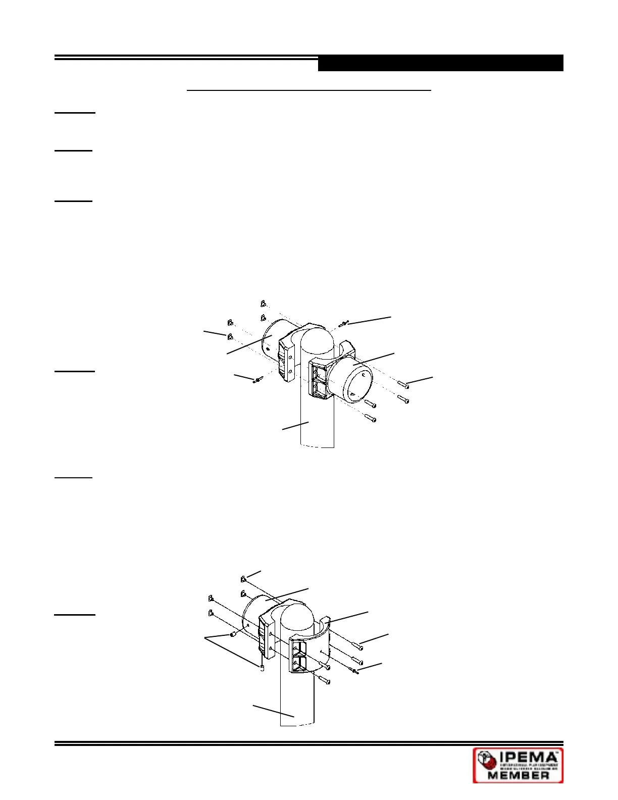
Remove existing saddle from the vertical post where the add-a-bay will attach. Replace it with one of the
receivers from the new add-a-bay kit. Attach new receiver to existing receiver using four 3/8”x2” security
TORX head bolts and four 3/8”x1/2” rectangular weld nuts (see Detail A) to make a new swing middle.
Make sure both sides of saddle/receiver are evenly spaced. No more than 2 threads may be showing.
Tighten hardware. NOTE: Drive pins will be installed in Step 6.
Vertical Post
3/8”x2” Security
TORX Bolt
3/8” Rectangular Weld Nut
1/4”x1” Drive Pin
(Installed in Step 6)
New 5” Receiver
1/4”x1” Drive Pin
(Installed in Step 6)
Existing 5” Receiver
Detail A
STEP 4
Select vertical post, one 5”x5” receiver, one 5” saddle (removed from existing end post), four 3/8”x1-3/4”
security TORX bolts and four 3/8”x1/2” rectangular weld nuts. With post laying on ground, attach receiver
and saddle to top of each post (even with edge of cap) using four bolts and four nuts each (see Detail B).
NOTE: Bolts will be inserted through saddle (weld nuts through receiver). Make sure both sides of saddle/
receiver are evenly spaced. No more than 2 threads may be showing. Tighten hardware. Set screws will
be installed in Step 5.
Vertical Post
3/8” Rectangular Weld Nut
3/8”x1-3/4” Security
TORX Head Bolt
1/4”x1” Drive Pin
(Installed in Step 6)
5” Saddle (from existing end post)
New 5” Receiver
1/2”x3/4” Set Screw
(Installed in Step 5)
Detail B
SINGLE 5” POST SWING FRAME - ADD-A-BAY
 Loading...