TWP/TWB200 – TWP/TWB9000
28
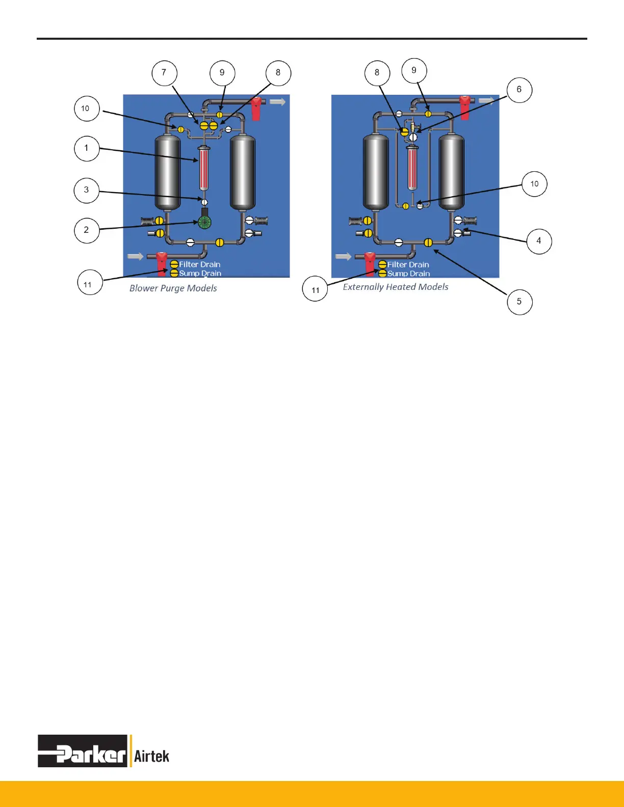
1. Heater Tube
Red when heater is active
2. Blower (Blower Purge Models Only)
Green when blower is running,
Red during Blower related alarms
3. Blower Flow Switch (Blower Purge Models Only)
Yellow – indicates lack of ow across ow switch
White – indicates lack of ow across ow switch
Yellow – indicates ow across blower ow switch
4. Exhaust Valves (2 or 4 depending on pre-exhaust)
White – indicates valve(s) are open
Yellow – indicates valves are closed
5. Inlet Valves (2)
White – indicates valve(s) are open
Yellow – indicates valves are closed
6. Purge Stop Valve (Externally Heated Models Only)
White – indicates valve(s) are open
Yellow – indicates valves are closed
7. 2% Purge Valve (Blower Purge ModelsOnly)
White – indicates valve(s) are open
Yellow – indicates valves are closed
8. Repressurization Valve
White – indicates valve(s) are open
Yellow – indicates valves are closed
9. Outlet Check Valves (2)
White – no air is owing thru valve
Yellow – air is owing thru valve
10. Purge Check Valves (2)
White – no air is owing thru valve
Yellow – air is owing thru valve
11. Drain Valves (Optional)
 Loading...