TWP/TWB200 – TWP/TWB9000
45
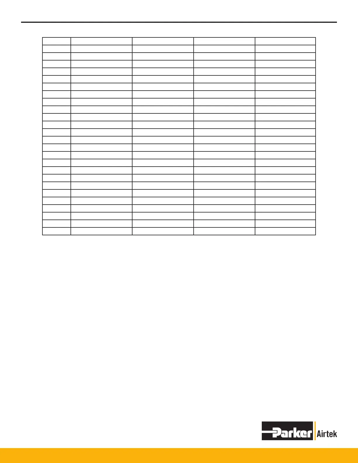
Pin Number Signal Signal Name Signal Direction Type
1 FG Frane Ground - -
2 TD Transmit ata Output RS232C
3 RD Receive Data Input RS232C
4 RTS Request to Send Output RS232C
5 CTS Clear to Send Input RS232C
6 DSR Data Set Ready Input RS232C
7 SG Signal Ground - 5V-/RS232C
8 DCD Data Carrier Detect Output RS232C
9 - - - -
10 - - - -
11 - - - -
12 TXDA Transmit Data Output RS422/RS485
13 TXDB Transmit Data Output RS422/RS485
14 RTSA Request to Send Output RS422
15 RTSB Request to Send Output RS422
16 - - - -
17 - - - -
18 CTSA Clear to Send Input RS422
19 CTSB Clear to Send Input RS422
20 DTR Data Terminal Ready Output RS232C
21 5 V + 5 V Power Supply + Output -
22 RI Ring Indicator Input RS232C
23 - - - -
24 RXDA Receive Data Input RS422
25 RXDB Receive Data Input RS422
Notes: Settings are not checked for proper range. Bounds checking must be done in the controlling computer.
Setting a register outside of its stated range may result in unpredictable dryer operation.
DB25 Connector Pin-out
 Loading...