Bulletin 2751-001-M1/USA
Service Manual
HGA Hydraguide™
Hydraulics
Parker Hannifin Corporation
Hydraulic Pump/Motor Division
Greeneville, Tennessee
10
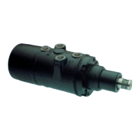
Exploded View
26. Ball
27. “O” Ring
28. Plug
29. Spacer
30. Drive Link
31. Rotor Set
31 a. Stator
31 b. Rotor
31 c. Spring
31 d. Vane
32. Manifold
33. Commutator Ring
34. Commutator
35. Seal Retainer
36. Seal
37. Washer
38. End Cover
39. Special Bolt
1. Nut
2. Dirt & Water Seal
3. Retaining Ring
4. Backup Washer
5. Seal
6. Screw
7. Upper Cover
8. Seal
9. Shim
10. Retaining Ring
11. Thrust Washer
12. Thrust Bearing
13. Thrust Washer
14. Spring Washer
15. Spacer
16. Input Shaft
17. Needle Roller
18. Drive Ring
19. Spacer
20. Torsion Bar
21. Needle Roller
22. Spool
23. Ball
24. Spring
25. Housing Assembly
25 a. Plug
25 b. “O” Ring
25 c. Ball
(*Items 2, 4, 5 included in HG500007 Kit)
(**Items sold in matched sets only)
Figure HGA-6
Vanes are specified on “HGA” units
with rotor widths smaller than 1.00.
* * *
 Loading...