Bulletin 2751-001-M1/USA
Service Manual
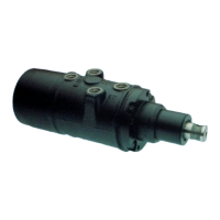
HGA Hydraguide™
Hydraulics
Parker Hannifin Corporation
Hydraulic Pump/Motor Division
Greeneville, Tennessee
19
Assembly Procedure
IMPORTANT; Before starting assembly, clean all
parts with clean petroleum base solvent and air
dry. Do not wipe dry with rags. Be sure all dried
paint chips have been removed from edges of
lapped surfaces. Unless otherwise indicated, DO
NOT oil parts before assembly.
1. Insert ball (26) into its cavity in the housing.
2. Install new “o” ring (27) on plug and roll-pin assem-
bly (28) and install in the housing (25) to 10-14 ft.
lbs. torque.
3. Reclamp housing (25) in the vise as shown in
Figure HGA-11.
4. Assemble thrust washer (13), thrust bearing (12),
thrust washer (11) and retaining ring (10) on input
shaft (16).
5. If the retaining spring (24) has been removed, install
a new retaining spring. The spring must fit tightly.
6. Insert actuator ball (23) into ball seat located
inside spool (22).
7. Assemble wave spring washer (14) over thrust
washer (13) and thrust bearing (12). Insert the
input shaft (16) into the spool, engaging the helix
and ball with a counter-clockwise motion. This
operation is best done while holding the spool in a
horizontal position.
8. Using the mid-section of the torsion bar (20) as a
gage, insert the gage between the spool end and
the thrust washer (13). (See Figure HGA-17). This
will position the spool in the necessary radial
relationship with the input shaft spline teeth for
assembly of drive ring (18).
9. Place the input shaft (16) and spool (22) assembly
in a vertical position, with the shaft end on the
table surface.
NOTE: Rotate the input shaft (16) out of the
valve spool (22) until input shaft will no longer
rotate. There will be a gap of approximately
.350 between end of valve spool (22) and thrust
washer (13) if the drive ring (18) is assembled
properly.
10. Insert the drive ring (18) into the spool (22) end by
visually aligning an internal space on the drive ring
with a tooth on the input shaft (16) split, and allow
the drive ring to drop to the limit of its travel. If the
drive ring does not engage the input shaft spline, a
slight rotation of the input shaft will allow the drive
ring to become fully engaged. Remove torsion bar
(20) gage. (See Figure HGA-18).
CAUTION: The HGA will not function properly if
the correct relationship of spool, drive ring and
input shaft is not achieved.
11. Install spacer (19) over torsion bar and pin
assembly (20) and insert the assembly into the
spool (22) end.
12. Align the cross-hole in the torsion bar (20) with the
cross-hole in the input shaft (16) and insert a .120
diameter pin punch to maintain alignment.
13. Insert the needle roller (17) into cross-hole in input
shaft (16); and while retracting the pin punch,
engage the pin in the torsion bar (20) cross-hole.
14. Initiate press of needle roller (17) into torsion bar
(20) with a few light impacts. Press needle roller
flush with outside diameter of input shaft (16) using
a 1/2” drive socket of 11/16 size for supporting the
input shaft. (See Figure HGA-19). With a few light
impacts on a .120 diameter pin punch, drive
needle roller (17) approximately 1/32 below the
input shaft (16) O.D. (See Figure HGA-12).
Figure HGA-17
Figure HGA-18
 Loading...