Bulletin 2751-001-M1/USA
Service Manual
HGA Hydraguide™
Hydraulics
Parker Hannifin Corporation
Hydraulic Pump/Motor Division
Greeneville, Tennessee
8
Hydraguide™ Steering
CONTROL VALVE
The control valve section contains a mechanically
actuated linear spool which is torsion bar centered.
The function of the control valve section is to direct fluid
to and from the metering section, and the cylinder, and
to regulate the pressure supplied to the cylinder. The
valve is provided with unique pressure chambers which
insure effective circuit isolation.
METERING SECTION
The metering section consists of a commutator and bi-
directional gerotor element, which contains an orbiting
rotor and a fixed stator. The commutator rotates at orbit
speed with the rotor and channels the fluid to and from
the rotor set and the valve section.
The rotor incorporates unique sealing vanes which are
spring and hydraulically forced into sealing contact
between the rotor and stator to reduce leakage across
the metering section.
The function of the metering section is to meter the oil to
the power cylinder, maintaining the relationship between
the hand wheel and the steered wheels. An additional
function of the metering section is to act as a manually
operated pump providing manual steering in the event of
an inoperative engine-driven pump.
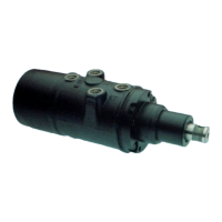
Figure HGA-2
ROTOR OPERATION IN THE ROTOR SET (See Fig. HGA-3)
Each lobe of the rotor has a diametrically opposite lobe, therefore, when one lobe is in a cavity its opposite lobe is
at the crest of the stator’s convex form opposite the cavity. As the rotor is rotated, each lobe in sequence is
moved out of its cavity to the crest of the stator’s convex form and this forces each opposite lobe, in sequence,
into a cavity. Due to the interaction between the rotor and the stator, there are 42 fluid discharging actions in one
revolution of the rotor. When the rotor is moving, fluid is always flowing out of three of the cavities while fluid is
flowing into three other cavities, and one of the cavities is inactive as it changes from one of discharging fluid to
one of admitting fluid. The commutator rotates with the rotor and channels the fluid to and from the valve section,
and to and from the rotor set.
Figure HGA-3
 Loading...