11
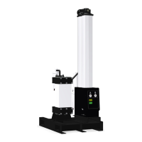
During normal operation, with unicells in place, the component
door (10) and the power pack door closed (3), the push rod (5)
is in contact with unicell endplate (6). Push rod extension (1) is
in contact with the ground bar (2) and bends to contact the limit
switch (4). Refer to Figure 9. Upon opening the component door
(10), the push rod (5) is released from the unicell endplate (6) and
spring (7) compression is relieved, breaking the contact of the
push rod extension (1) from the ground bar (2), placing AC volt-
age off line to the power pack and causing the grounding bar to
contact the acorn nut (8). Refer to Figure 10. When opening the
power pack door (3), the spring (7) remains compressed but the
grounding bar (2) is pulled from the push rod extension (1) as the
power pack door (3) is opened. AC voltage is placed off line to the
power pack by opening the limit switch (4) which the unicells are
grounded through the acorn nut (8), but with the contact spring
(12) fully compressed. Refer to Figure 11.
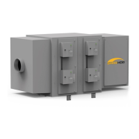
4.1.10 Odor Control
Odor filtration removes troublesome gases from the air stream
as a post treatment to the PSG unicell components. The media
can consists of carbon (18 to 20 pounds per filter) or potassium
permanganate (28 to 30 pounds per filter) a Class 1 rated media
which does not support combustion. PSG systems requiring an
ETL listing will have potassium permanganate.
The odor control cabinet consists of a number of odor filters as
dictated by size of the PSG system. The odor filter dimension is
22” x 22” x 2” at a designed velocity of 50 – 100 fpm. The life of
the media is generally three to six months with a proper primary
filtration (unicell components) maintenance program. Contaminant
collection to the odor filters will decrease the service interval. The
original filter frames should be retained. There is a slide gate to the
filter frame for dumping the spent media and installing new media.
A service company should be selected which is familiar with install-
ing new media into the original filter frames.
The odor filters should be installed one to two days prior to
placing the system on line. The odor filter service life will decrease
if the odor filters are installed before the one to two days recom-
mendation.
Figure 9
Component Door and Power Pack Door Closed
Figure 10
Component Door Open and
Power Pack Door Closed
Figure 11
Component Door Closed and Power Pack Door Open
• Remove plastic sleeves
• Slide odor filters into the cabinet tracks with gaskets parallel to the
back of the cabinet, and such that gaskets on adjacent filters seal
against each other.
• Odor filters are installed in a “V” bank configuration.
• Do not slide the filters with the gasket(s) in the filter tracks.
 Loading...