28
• On/Off switch (3)
• Switch on: Push the on/off switch
(3) forward and press it down to
lock it.
• Switch off: Press the on/off switch
(3) at the back, the on/off switch
jumps back to the off position.
Connecting dust extraction
Notes
• Do not use the tool without a dust ex-
tractor connected.
• Make sure that the workplace is well
ventilated.
• The dust bag can be easily emptied us-
ing the zip fastener at the back of the
dust bag (4).
Connecting/removing the dust ex-
traction (Fig.A)
1. Push the suction nozzle (5) into the
connection of the dust extraction (18).
2. Enlarge clamps: Press the two ends of
the clamp (19) together.
Attach the dust bag to the suction
nozzle by placing the clip (19) on the
dust bag (4) in the groove (20) on the
extraction nozzle (5).
3. Remove dust extraction: Pull the suction
nozzle (5) with collection bag (4) out
of the dust extraction connection (18).
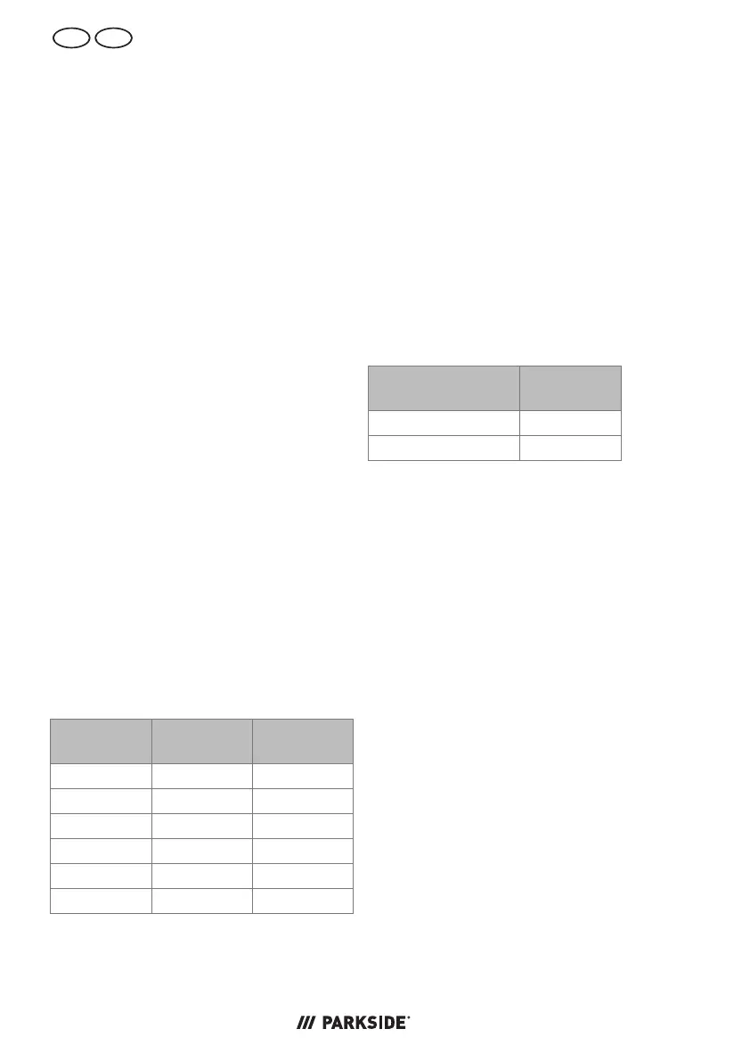
Setting the milling depth
Engage-
ment height
Flat dowel Milling
depth
0 No. 0 8 mm
10 No. 10 10 mm
20 No. 20 12.3 mm
S Simplex 13 mm
D Duplex 14.7 mm
MAX − 20 mm
Procedure (Fig.B)
1. Pull out the device plug out of the
power outlet.
2. Set the desired milling depth with the
dial (21).
The designations on the dial (21) indic-
ate the flat dowel sizes.
3. Push the drive motor (7) towards the
workpiece to check the set milling
depth.
4. You can readjust the milling depth set-
ting with the fine adjustment screw
(22). Use a Phillips screwdriver (not in-
cluded) for this purpose.
Direction of rota-
tion
Milling
depth
Screw (22) ⭮ Reduce
Screw (22) ⭯ Increase
Adjusting the height stop
Notes
• The height stop (13) lets you set the
distance between the top of the work-
piece and the groove to be milled.
• After loosening the locking screw (14),
the height stop (13) can be removed
upwards and reinserted at any time.
Procedure
1. Pull out the device plug out of the
power outlet.
2. Loosen ⭯ the locking screw for the
height adjustment (14).
3. Use the height dial (12) to set the de-
sired height on the height adjustment
scale (16).
To position the groove in the centre of
the workpiece, the height stop (13)
must be set to half the thickness of the
workpiece.
NOTICE! Example: For a 20 mm thick
workpiece, set 10 mm on the scale
(16).
 Loading...