EasyManua.ls Logo

Parkside PSKO 24 B2 - User Manual

Parkside PSKO 24 B2
108 pages
Print Icon
To Next Page IconTo Next Page
Loading...
8
QUIET COMPRESSOR PSKO 24 B2
LEISE-KOMPRESSOR PSKO 24 B2
COMPRESSEUR SILENCIEUX PSKO 24 B2
IAN 373211_2104
CHAT
LEISE-KOMPRESSOR
Bedienungs- und Sicherheitshinweise
Originalbetriebsanleitung
DE
BE
STILLE COMPRESSOR
Bedienings- en veiligheidsinstructies
Vertaling van de originele handleiding
NL
QUIET COMPRESSOR
Operating and Safety Instructions
Translation of Original Operating Manual
GB IE
BE
COMPRESSEUR SILENCIEUX
Consignes d‘utilisation et de sécurité
Traduction des instructions d’origine
FR
CICHY KOMPRESOR
Wskazówki dotycce obsługi i bezpieczeństwa
Tłumaczenie oryginalnej instrukcji obsługi
PL
TICHÝ KOMPRESOR
Pokyny pre obsluhu a bezpnostné pokyny
Preklad originálnehovodu na obsluhu
SK
TICHÝ KOMPRESOR
Pokyny pro obsluhu a bezpnostní pokyny
Překlad originálního provozního návodu
CZ
COMPRESOR SILENCIOSO
Instrucciones de utilización y de seguridad
Traducción del manual de instrucciones original
ES
STØJSVAG KOMPRESSOR
Drifts- og sikkerhedsinstruktioner
Oversættelse af den originale driftsvejledning
DK

Table of Contents

Question and Answer IconNeed help?

Do you have a question about the Parkside PSKO 24 B2 and is the answer not in the manual?

Overview

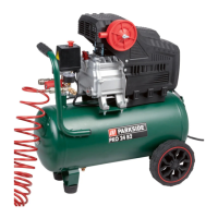
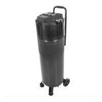
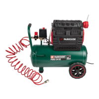
This document describes the Parkside Quiet Compressor PSKO 24 B2, a device designed for generating compressed air for various pneumatic tools.

Function Description:

The compressor is designed to generate compressed air for tools that operate with compressed air, such as tire inflators, blow-out pistols, and paint spray guns. It is suitable for tools with an air volume of up to approximately 150 l/min. However, due to its limited air output, it is not recommended for tools with very high air consumption, such as orbital sanders, die grinders, or hammer screwdrivers. The compressor is intended for indoor use in dry and well-ventilated spaces.

The device features a transport handle (1), a pressure switch (2), and an on/off switch (3). It includes an air filter (4) with a filter housing (4a), filter element (4b), and filter cover (4c), connected by a hose (4d). For mobility, it has wheels (5) with fillister head screws (5a) and washers (5b). A drain screw for condensate (6) is located at the bottom of the pressure vessel (8), which is supported by a supporting foot (7) with a screw (7a). The compressor is equipped with a safety valve (9) that includes an exhaust nut (9a), a connection lock (9b), and a cap for the exhaust nut (9c). Compressed air is delivered via two quick couplings (10, 11) for regulated compressed air. Pressure gauges (12, 13) display the set pressure and vessel pressure, respectively. A compressed air hose (14) with a plug nipple (14a) and quick coupling (14b) is provided for connecting tools. A pressure regulator (15) allows for adjusting the pressure. A transport lid (16) is also included.

Important Technical Specifications:

  • Mains connection: 230 V~ 50 Hz
  • Motor power: 1500 W
  • Operating mode: S1
  • Compressor speed: 2850 min⁻¹
  • Pressure vessel capacity: approx. 24 l
  • Operating pressure: approx. 8 bar
  • Theoretical intake capacity: approx. 257 l/min
  • Effective delivery quantity at 7 bar: approx. 80 l/min
  • Effective delivery quantity at 4 bar: approx. 110 l/min
  • Effective delivery quantity at 1 bar: approx. 150 l/min
  • Sound pressure level (LPA): 68 dB(A)
  • Sound power level (LWA): 86 dB(A)
  • Uncertainty (KPA/WA): 2.19 dB
  • Protection category: IP30
  • Device weight: approx. 24.8 kg
  • Max. altitude (above mean sea level): 1000 m

Usage Features:

Before commissioning, the device must be fully assembled. This involves fitting the wheels (5) and the supporting foot (7) as shown in the illustrations. The air filter (4) needs to be screwed onto the equipment after removing the transport lid (16), and the hose (4d) inserted into its opening. The compressor connects to a standard 230 V~ 50 Hz protective contact socket with 16 A fuse protection. The on/off switch (3) is used to start and stop the compressor. The pressure regulator (15) allows users to set the desired pressure, which is displayed on the pressure gauge (12). The vessel pressure can be read from the pressure gauge (13). The pressure switch (2) is factory-set with a cut-in pressure of approximately 5.5 bar and a cut-out pressure of approximately 8 bar. The compressed air hose (14) is connected by attaching its plug nipple (14a) to one of the quick couplings (10, 11), and then connecting the compressed air tool to the hose's quick coupling (14b). The device includes a thermal protector that automatically switches off the motor in case of overload. If tripped, the user should unplug the device, wait a few minutes for it to cool down, and then plug it back in. If the device still does not start, the on/off switch (3) should be toggled.

Maintenance Features:

Regular cleaning, maintenance, and storage are crucial for the device's longevity and safe operation.

  • Cleaning: The device should be kept free of dust and dirt, wiped with a clean cloth, or blown off with low-pressure compressed air after each use. A damp cloth with mild soap can be used for regular cleaning, but aggressive cleaning agents or solvents should be avoided. The hose and injection tools must be disconnected from the compressor before cleaning.
  • Pressure Vessel Maintenance: To ensure a long service life for the pressure vessel (8), condensate must be drained after each use by opening the drain screw (6). Before draining, the vessel pressure should be released. The drain screw (6) is opened by turning it anti-clockwise. The vessel should be tilted slightly to ensure complete drainage. The pressure vessel (8) should be checked for rust and damage before each use.
  • Safety Valve Maintenance: The safety valve (9) is factory-set and should not be adjusted. It must be actuated every 30 operating hours (at least 3 times a year) to ensure proper function. This involves turning the perforated exhaust nut (9a) anti-clockwise and pulling the valve rod outwards to open the outlet, then tightening the nut again.
  • Air Filter Cleaning: The air filter (4) prevents dust and dirt from being sucked in and must be cleaned at least every 300 operating hours. A blocked filter significantly reduces compressor power. Cleaning involves turning the air filter (4) anti-clockwise to remove it, opening the filter cover (4c), removing the filter element (4b), tapping out the components, blowing them out with compressed air (approx. 3 bar), and reassembling in reverse order.
  • Storage: The compressor should be stored in a dry location inaccessible to unauthorized persons, always upright, and never tilted. Before storage, the mains plug should be pulled out, and the equipment and all connected pneumatic tools should be ventilated. Excess pressure in the pressure vessel (8) should be released by switching off the compressor and consuming the remaining compressed air with a tool running in idle mode or a blow-out pistol.

Parkside PSKO 24 B2 Specifications

General IconGeneral
BrandParkside
ModelPSKO 24 B2
CategoryAir Compressor
LanguageEnglish

Related product manuals