EasyManua.ls Logo

Parrot MKi + Parrot CK3100 range 2008 User Manual

Parrot MKi + Parrot CK3100 range 2008
13 pages
To Next Page IconTo Next Page
Page #1 background imageLoading...
Page #1 background image
This sheet is designed to help you with the installation of a Parrot product and is provided purely for information purposes. The installer is
solely responsible for any installation carried out in accordance with the instructions in this sheet and for the quality of the installation. All
rights reserved © Copyright 2011 PARROT SA, a French Société Anonyme (Public Limited Company) Registered on the Paris Trade and
Companies Register under No. 394 149 496 Reproduction not permitted without authorisation from Parrot SA. Images not contractually
binding.
5008
5008
Installation manual:
Parrot MKi + Parrot
CK3100 range
The brand name PEUGEOT 5008 and the PEUGEOT logo are the property of AUTOMOBILES PEUGEOT.
This document is only valid for the vehicle model 5008® year 2009 to 2011, excluding all other models in the same range and excluding later
modifications made to the vehicle by the manufacturer.
The Parrot brand name and logos are the exclusive property of Parrot SA.
Question and Answer IconNeed help?

Do you have a question about the Parrot MKi + Parrot CK3100 range 2008 and is the answer not in the manual?

Parrot MKi + Parrot CK3100 range 2008 Specifications

General IconGeneral
CategoryAutomobile Accessories
BluetoothYes
External MicrophoneYes
Voice RecognitionYes
Audio streaming profileA2DP
Remote control profileAVRCP
Noise cancellationYes
Music StreamingYes
Bluetooth version2.0
Phonebook access profilePBAP
Operating range10 meters
Supported languagesMultiple
CompatibilityBluetooth-enabled phones
Power supply12V
DisplayLCD display

Summary

Disassembly Steps 1-6

Radio Removal

Steps to detach the car radio, including disconnecting the connector and antenna.

Disassembly Steps 7-8

Finding an ACC Wire

DIAG Socket Connection

Procedure for uncliiping and accessing the DIAG socket for wire connection.

Microphone Cable Routing

Microphone Cable Routing Continued

Accessory Cable Feeding

Hands-Free System Fitting

Adaptor and Connector

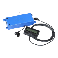
Connecting the adaptor to the original connector and wiring to the blue box.

Wiring Diagram

Diagram showing ISO adapter connections for ignition, battery, ground, and line-out.

Hands-Free System Fitting Continued

Testing the Installation

System Activation Check

Verifying menu display, muting, and sound output from speakers.

Power Off and Fuse Check

Checking kit powers off and 'goodbye' message; reversing fuses if needed.

Phone Pairing and Call Test

Pairing a telephone and making a call to test microphone and kit functionality.

Reassembly Procedure

Radio and Antenna Refitting

Reconnect adaptor and antenna, refit radio with blue box and cables on top.

Related product manuals