9
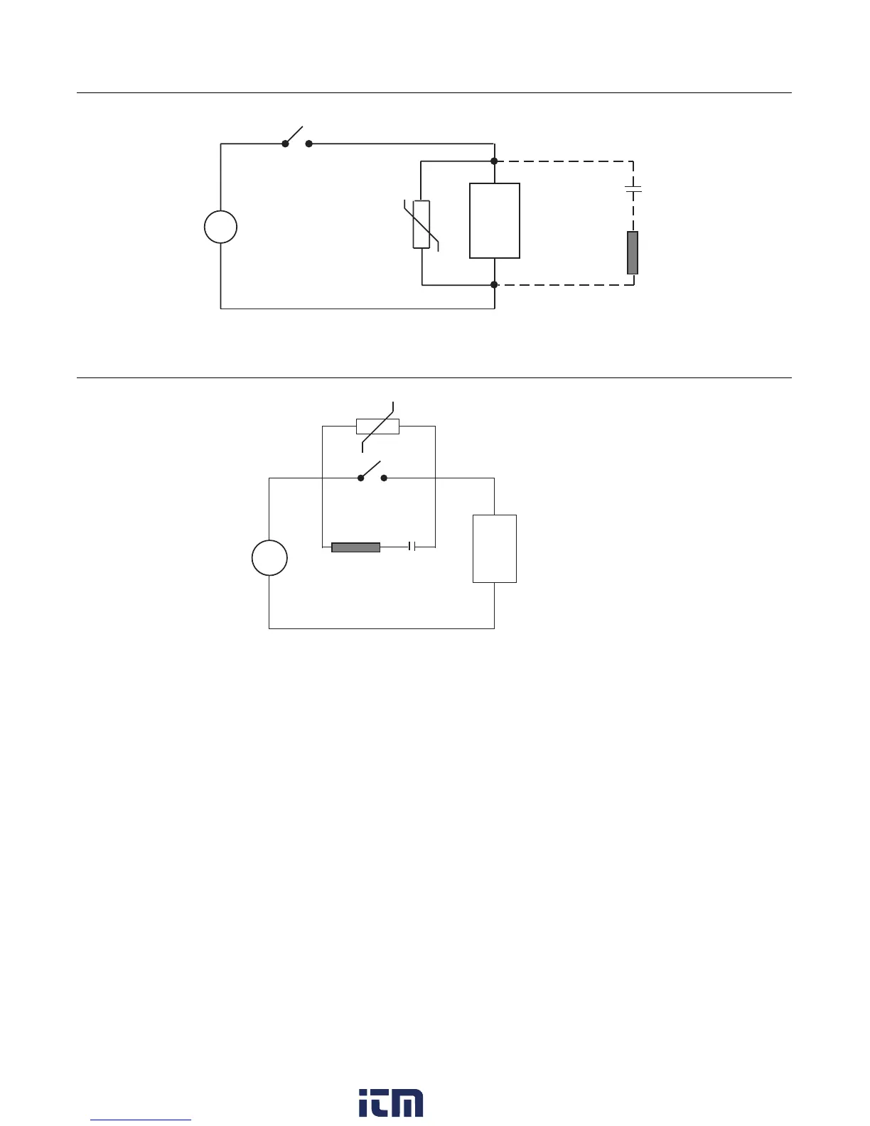
FIGURE 2-2
FIGURE 2-3
2.3.1 SENSOR PLACEMENT
If the input probe will be subjected to corrosive or abrasive conditions, it should be protected by the appropriate thermowell.
The probe should be positioned to reflect the true process temperature:
In liquid media - the most agitated area
In air - the best circulated area
For thermocouple sensors, the lead resistance should not exceed 300 ohms. If this is exceeded, recorder accuracy could be
affected. To determine the temperature error caused by lead length resistance, use the following equation:
Terr = TCe x L where; TCe = temperature error in °F or °C per 1000 feet
L = length of lead wire in thousands of feet
A.C.
MOV
Inductive
Load
C
R
A.C.
MOV
R
Inductive
Load
C
w ww . . co m
information@itm.com1.800.561.8187