Do you have a question about the Partner SP-630-Q and is the answer not in the manual?
Potential radio interference in domestic use and user responsibility for measures.
Device meets FCC Part 15 limits for commercial environments.
Perchlorate in battery and mercury in LCD lamps require special handling/disposal.
Compliance with EEC directives for EMC and Low Voltage.
Risk of explosion if wrong battery type is used for replacement.
Table of hazardous substances in components per GB/T 26572 limits.
Qualified personnel, static discharge, handling boards by edges, inverter safety.
Immediate washing and medical attention if LCD fluid contacts skin or eyes.
Manual protection, disclaimer on changes, and trademark acknowledgment.
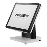
Advice on saving packaging and unpacking the machine terminal.
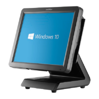
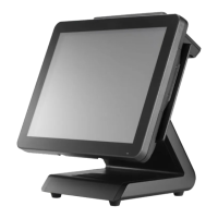
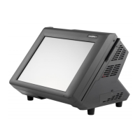
Identifies components on the front-right side of the device.
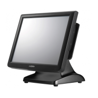
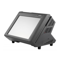
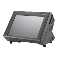
Identifies components on the rear side of the device.
Details COM, VGA, Microphone, and Audio ports.
Details USB, RJ11, DC, LAN, LPT, and SATA connections.
Defines pin assignments for COM, VGA, and USB 2.0 connectors.
Defines pin assignments for RJ-11, DC 12V input/output, and LAN connectors.
Defines pin assignments for USB 3.0, SATA, and Parallel connectors.
Configuration for LVDS power, VDD select, and CMOS clearing.
Configuration for COM power select and Touch Panel interface.
Identifies connectors for power, MSR, SATA, and parallel ports.
Identifies connectors for LCD, Speaker, and Touch Panel.
Overview of BIOS functions and usage scenarios.
Displays system info and how to set time/date.
Settings for ACPI, hibernation, and sleep states.
Settings for power features, touch control, and chassis intrusion.
Settings for serial and parallel port enablement and modes.
Parallel port modes, serial voltage, and hardware status monitoring.
Settings for CPU features, virtualization, and power management.
Settings for SATA modes and USB legacy support.
Enables or disables Intel Trusted Execution Engine (TXE) support.
Settings for System Agent and graphics configuration.
Adjusts graphics memory allocation and LCD panel properties.
Settings for EMI reduction and memory details.
Settings for onboard LAN, PCI-e, and USB devices.
Settings for XHCI (USB 3.0) and EHCI (USB 2.0) support.
Procedures for setting, changing, or clearing user passwords.
Settings for OS selection, boot order, and boot options.
Options to save changes, discard, or load optimized defaults.
Instructions for automatic driver installation from CD/USB.
Steps to install the Intel Chipset Device Software.
Completing the Intel Chipset Driver installation.
Steps to install the Intel Graphics Media Accelerator Driver.
Completing the Intel Graphics Driver installation.
Steps to install the Realtek Ethernet Controller Driver.
Completing the LAN Driver installation.
Steps to install the eGalaxTouch screen driver.
Completing the eGalaxTouch driver installation.
Configuration steps for eGalaxTouch driver.
Selecting destination and program folders for eGalaxTouch.
Selecting installation features for eGalaxTouch.
Finalizing eGalaxTouch driver installation and restart.
Steps to launch the touchscreen calibration utility.
Guide to the 4-point touchscreen calibration process.
Finalizing the 4-point touchscreen calibration.
General procedures for identifying and verifying symptoms.
Steps to check cash drawer issues, noting RJ-11 voltage.
Lists LCD display problems and their solutions.
Lists issues and solutions for touch, power, and network.
Lists issues and solutions for USB, peripherals, and boot problems.
Guidelines for a clean environment, tools, and handling.
Notes on symptom persistence, part removal order, and screw usage.
Steps to replace the MSR and customer display.
Steps to remove and replace the Hard Disk Drive.
Steps to remove and replace the LCD panel.
Steps to remove and replace the speaker.
Steps to remove and replace the power button.
Steps to replace memory module and coin cell battery.
Steps to remove and replace the I/O shield.
Steps to replace the mainboard and heatsink.
Steps to replace panel bracket, touch, and LCD panels.
Visual representation of component assembly.
Detailed list of internal parts and item numbers.
Exploded views of VFD, MSR, and PM-116 modules.
Detailed list of peripheral parts and item numbers.
Comprehensive technical specifications of the POS terminal.
| Brand | Partner |
|---|---|
| Model | SP-630-Q |
| Category | Touch terminals |
| Language | English |