www.parweld.com www.parweld.com
7
5.3 Input and grounding connection
WARNING
Before starting the installation, check that your power supply
is adequate for the voltage, amperage, phase, and frequency
specied on the Machine nameplate.
Operate the welding power source from a single-phase 50/60 Hz,
AC power supply. The input voltage must match one of the electrical
input voltages shown on the input data label on the unit nameplate.
The input voltage is switchable between 110 or 240V ensure the
correct voltage is shown before connection the power supply. Do
not attempt to change the input voltage selector with the power on.
Refer to the specications table for voltage tolerances.
Have a qualied electrician connect the input plug. For long runs
over 30m , larger copper wires should be used. The green/yellow
wire in the input cable connects to the frame of the machine. This
ensures proper grounding of the machine when the machine plug is
inserted into the receptacle.
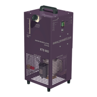
5.4 Output Connections
The Red Connection is the hot water return connection and should
be connected to the red hose on the welding torch or if connected
through the power source to the water drain connection.
The Blue Connection is the cold water supply connection and
should be connected to the blue hose on the welding torch or if
connected through the power source to the water supply connection.
Both hose connections are Type 21 Quick connections, if the water
cooler is mounted away from the power source/torch a hook up
extension kit my be used, refer to the parts list.
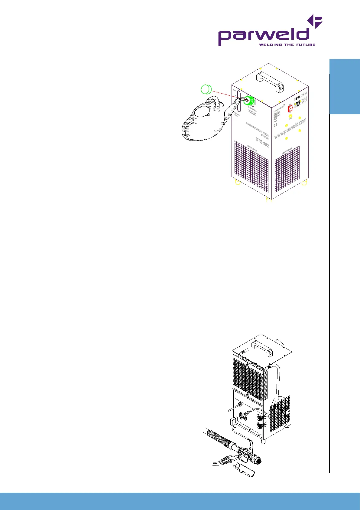
5.5 Coolant ling
Remove the ller cap (4) and ll the unit with Parweld UltraCool
until the Max mark is reached in the sight glass. Secure the ller
cap before starting the unit. There is not need to prime the pump
but on rst running the pump should be allowed to run with the torch
connected for 1 minute to ensure all air has been expelled from the
system before welding is started. After initial running rell the water
tank to the Max level.
Warning
Operating the unit without the use of Parweld
UltraCool will shorten the life of the pump and torch. UltraCool
contains special additive to lubricate the pump and prevent corrosion
in all parts of the system including the torch.
Glycol based uids should not be used as they
promote corrosion due to the electrical conductivity of the uid.
6.0 Flow switch (XTS-902F)
The XTS-902F is supplied tted with a ow switch
, this can also be purchased as a retrot kit for the XTS-902. The
purpose of the ow switch is to prevent damage to the torch or
hoses due to a loss of water ow or failure to switch on the water
cooler. In order for the ow switch to operate correctly it must be
linked into the welding control circuit this can be done as shown
below or by wiring the control wires in series with the trigger wires
inside the power source.
Warning
Machine modications should only be performed by competent
persons.
If the water ow falls below 1lpm then the ow switch
will operate and break the trigger circuit so stopping the welding
process. If the ow switch operates there may be an number of
causes refer to the fault nding section.
OPERATION