1
SERIES
3000
INTEGRATED
AMPLIFIER
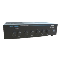
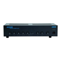
AX3040 - 40 W
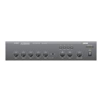
AX3060 - 60 W
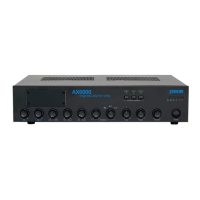
AX3120 - 120 W
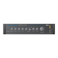
AMPLIFICATORI INTEGRATI
INTEGRATED AMPLIFIERS
AMPLIFICATEURS INTEGRES
SERIE
SERIES
3000
SOMMARIO
1 Descrizione generale
1.1 Introduzione ................................... 3
1.2 Pannello frontale ............................ 6
1.3 Pannello posteriore ........................ 6
1.4 Schema a blocchi........................... 6
1.5 Installazione ................................... 7
1.6 Alimentazione e messa a terra ...... 7
1.7 Montaggio in rack........................... 7
2 Avvertenze
2.1 Note di sicurezza ........................... 8
2.2 Criteri generali ............................... 8
3 Connessioni
3.1 Ingressi microfonici ........................ 9
3.2 Ingresso ausiliario .......................... 9
3.2.1 Ingresso CD ................................... 9
3.3 Ingresso MIC3/AUX1 ..................... 9
3.4 Precedenza .................................... 9
3.5 Ingresso telefono/emergenza ....... 10
3.6 Uscita di segnale .......................... 10
3.7 Uscite di potenza .......................... 10
3.7.1 Sistemi a bassa impedenza .......... 11
3.7.2 Sistemi a tensione costante .......... 11
3.7.3 Calcolo del numero di
diffusori (tramite le potenze) ........ 12
3.7.4 Calcolo del numero di
diffusori (tramite le impedenze) .... 12
4 Uso dell’apparecchio
4.1 Accensione ................................... 13
4.2 Correzione acustica ...................... 13
4.2.1 Controllo toni bassi ....................... 13
4.2.2 Controllo toni acuti ........................ 13
4.3 DIN-DON....................................... 14
4.4 Condizioni di
sovraccarico e protezione ............. 14
5 Parti di ricambio ......................... 15
6 Caratteristiche tecniche ............. 16
TABLE OF CONTENTS
1 General description
1.1 Introduction .................................... 3
1.2 Front panel ..................................... 6
1.3 Rear panel ..................................... 6
1.4 Block diagram................................. 6
1.5 Installation ...................................... 7
1.6 Power supply and
ground connection ......................... 7
1.7 Rack mounting ............................... 7
2 Warnings
2.1 Safety notes ................................... 8
2.2 General features............................. 8
3 Connections
3.1 Microphone inputs.......................... 9
3.2 Auxiliary input................................. 9
3.2.1 CD input ......................................... 9
3.3 MIC3/AUX1 input............................ 9
3.4 Precedence .................................... 9
3.5 Telephone/emergency input .......... 10
3.6 Signal output ................................. 10
3.7 Power outputs................................ 10
3.7.1 Low impedance systems............... 11
3.7.2 Constant voltage systems ............. 11
3.7.3 Determining the number of
speakers (through power values) .. 12
3.7.4 Determining the number of speakers
(through impedance values) ............ 12
4 Operation
4.1 Power on ....................................... 13
4.2 Acoustic correction........................ 13
4.2.1 Bass control .................................. 13
4.2.2 Treble control ................................. 13
4.3 CHIME........................................... 14
4.4 Overload and
protection conditions ..................... 14
5 Spare parts .................................. 15
6 Technical specifications ............. 16
SOMMAIRE
1 Description générale
1.1 Introduction ................................... 17
1.2 Panneau avant .............................. 18
1.3 Pannello arriêre ............................. 18
1.4 Schéma fonctionnel ...................... 18
1.5 Installation ..................................... 19
1.6 Alimentation et mise à la terre ...... 19
1.7 Montage sur rack .......................... 19
2 Precautions
2.1 Notices de sécurité ....................... 20
2.2 Criteres généraux ......................... 20
3 Connexions
3.1 Entrées micro ................................ 21
3.2 Entrée auxiliaire ............................ 21
3.2.1 Entrée CD ..................................... 21
3.3 Entrée MIC3/AUX1........................ 21
3.4 Précédence ................................... 21
3.5 Ingresso telefono/emergenza ....... 22
3.6 Sortie de signal ............................. 22
3.7 Sorties de puissance ................... 22
3.7.1 Systèmes à basse impedance ...... 23
3.7.2 Systèmes à tension constant ........ 23
3.7.3 Calcul du nombre des
diffuseurs (par les puissances) ..... 24
3.7.4 Calcul du nombre des
diffuseurs (par les impédances) ... 24
4 Utilisation de l’appareil
4.1 Mise en marche ............................ 25
4.2 Correction acoustique ................... 25
4.2.1 Contrôle tonalites basses ............. 25
4.2.2 Contrôle tonalites aigues .............. 25
4.3 INDICATIF MUSICAL .................... 26
4.4 Conditions de surcharge
et protection .................................. 26
5 Liste des pieces detachées ....... 27
6 Caractéristiques techniques...... 28