SERIE 5000
10
CONNECTIONS
3CONNESSIONI
3.10 SELEZIONE DI ZONE DASCOLTO
Gli amplificatori della Serie 5000 dispongono della possibilità di
inserire/disinserire in modo indipendente fino a tre zone di diffusione
tramite gli interruttori ZONE 1, ZONE 2 e ZONE 3 [1]. In questo caso,
le tre zone di diffusori devono essere connesse alla morsettiera [24],
tenendo sempre conto del carico nominale massimo ammesso
dallapparecchio (vedi par. 3.8.2).
É inoltre possibile selezionare contemporaneamente tutte le zone dascolto
tramite linterruttore ALL. Le selezioni effettuate tramite gli interruttori
[1] sono confermate dallaccensione delle relative spie luminose.
Gli interruttori interrompono il collegamento delle linee a tensione
costante sui terminali della morsettiera [24].
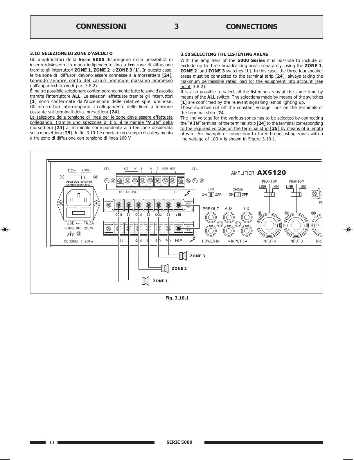
La selezione della tensione di linea per le zone deve essere effettuata
collegando, tramite uno spezzone di filo, il terminale V IN della
morsettiera [24] al terminale corrispondente alla tensione desiderata
sulla morsettiera [25]. In fig. 3.10.1 è riportato un esempio di collegamento
a tre zone di diffusione con tensione di linea 100 V.
3.10 SELECTING THE LISTENING AREAS
With the amplifiers of the 5000 Series it is possible to include or
exclude up to three broadcasting areas separately, using the ZONE 1,
ZONE 2 and ZONE 3 switches [1]. In this case, the three loudspeaker
areas must be connected to the terminal strip [24],
always taking the
maximum permissible rated load for the equipment into account (see
point 3.8.2).
It is also possible to select all the listening areas at the same time by
means of the ALL switch. The selections made by means of the switches
[1] are confirmed by the relevant signalling lamps lighting up.
These switches cut off the constant voltage lines on the terminals of
the terminal strip [24].
The line voltage for the various zones has to be selected by connecting
the V IN terminal of the terminal strip [24] to the terminal corresponding
to the required voltage on the terminal strip [25] by means of a length
of wire. An example of connection to three broadcasting zones with a
line voltage of 100 V is shown in Figure 3.10.1.
Fig. 3.10.1
INPUT 5 INPUT 4 INPUT 3 MI
 Loading...