4
P8036
2.2 Note di sicurezza
La rimozione del coperchio dell'apparecchio presenta il rischio di scosse
elettriche. Ogni intervento all'interno dell'apparecchio deve essere
eseguito da personale specializzato. Prima di procedere alla
sostituzione dei fusibili, accertarsi di avere staccato il cavo di rete e
leventuale alimentazione secondaria. La sostituzione deve essere
effettuata con fusibili dello stesso tipo e valore. Non rimuovere mai il
conduttore di terra dal cavo di rete. Ad evitare il pericolo di scosse
elettriche o guasti, non introdurre oggetti specialmente se metallici,
attraverso le aperture dell'apparecchio. Nel caso di accidentale caduta
di liquidi sull'apparecchio, staccare immediatamente la spina di rete ed
interpellare il centro di assistenza PASO più vicino.
IMPORTANTE!
La PASO declina ogni responsabilità per danni a cose e/o persone
derivanti dall'uso non corretto dell'apparecchio o da procedure non
rispondenti a quanto riportato sul presente libretto.
2. AVVERTENZE GENERALI
2.1 Installazione
Tutti gli apparecchi PASO sono costruiti nel rispetto delle più severe
normative internazionali di sicurezza ed in ottemperanza ai requisiti
della Comunità Europea. Per un corretto ed efficace uso dellunità P8036
è importante prendere conoscenza di tutte le caratteristiche leggendo
attentamente le presenti istruzioni ed in particolare le note di sicurezza.
Durante il funzionamento dellapparecchio è necessario assicurare
unadeguata ventilazione. Evitare di racchiudere il P8036 in un mobile
privo di aerazione o di tenerlo in prossimità di sorgenti di calore.
Assicurarsi che tutti gli ingressi e le uscite siano correttamente collegati
prima dellaccensione. Questo apparecchio è predisposto per il montaggio
in mobile rack standard 19.
2.3 Alimentazione e messa a terra
Lapparecchio é predisposto per il funzionamento con tensione di rete a
230 V ± 10%, 50/60 Hz. In alternativa, è previsto il funzionamento
con una tensione continua esterna di 24V applicabile ai relativi
morsetti [9]. In accordo con le normative di sicurezza, linterruttore di
accensione [7] agisce solo sulla tensione di rete. Lapparecchio é corredato
di cavo di alimentazione con filo di messa a terra ed il relativo terminale
sulla spina di rete non deve essere rimosso in alcun caso. Assicurarsi che
la presa di corrente sia dotata di collegamento di terra a norme di legge.
3. CONNESSIONI
Allunità di controllo P8036 è possibile collegare fino ad un massimo di 5
basi B613 e/o B616. Vengono di seguito illustrate le due modalità di
utilizzo dellapparecchio.
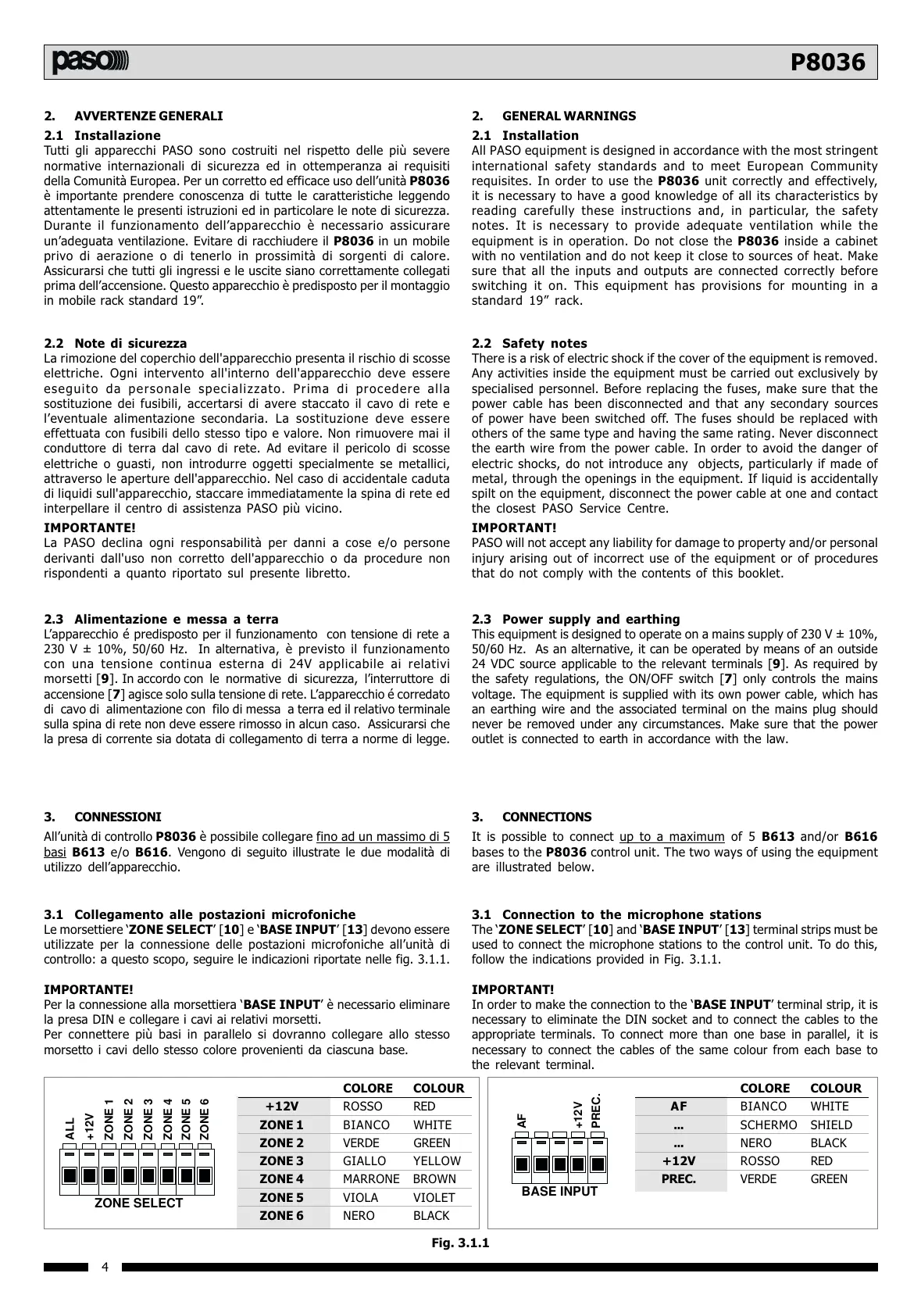
3.1 Collegamento alle postazioni microfoniche
Le morsettiere ZONE SELECT [10] e BASE INPUT [13] devono essere
utilizzate per la connessione delle postazioni microfoniche allunità di
controllo: a questo scopo, seguire le indicazioni riportate nelle fig. 3.1.1.
IMPORTANTE!
Per la connessione alla morsettiera BASE INPUT è necessario eliminare
la presa DIN e collegare i cavi ai relativi morsetti.
Per connettere più basi in parallelo si dovranno collegare allo stesso
morsetto i cavi dello stesso colore provenienti da ciascuna base.
BASE INPUT
AF
+12V
PREC.
ZONE SELECT
ALL
+12V
ZONE 1
ZONE 2
ZONE 3
ZONE 4
ZONE 5
ZONE 6
Fig. 3.1.1
COLORE COLOUR
+12V ROSSO RED
ZONE 1 BIANCO WHITE
ZONE 2 VERDE GREEN
ZONE 3 GIALLO YELLOW
ZONE 4 MARRONE BROWN
ZONE 5 VIOLA VIOLET
ZONE 6 NERO BLACK
COLORE COLOUR
AF BIANCO WHITE
... SCHERMO SHIELD
... NERO BLACK
+12V ROSSO RED
PREC. VERDE GREEN
2.2 Safety notes
There is a risk of electric shock if the cover of the equipment is removed.
Any activities inside the equipment must be carried out exclusively by
specialised personnel. Before replacing the fuses, make sure that the
power cable has been disconnected and that any secondary sources
of power have been switched off. The fuses should be replaced with
others of the same type and having the same rating. Never disconnect
the earth wire from the power cable. In order to avoid the danger of
electric shocks, do not introduce any objects, particularly if made of
metal, through the openings in the equipment. If liquid is accidentally
spilt on the equipment, disconnect the power cable at one and contact
the closest PASO Service Centre.
IMPORTANT!
PASO will not accept any liability for damage to property and/or personal
injury arising out of incorrect use of the equipment or of procedures
that do not comply with the contents of this booklet.
2. GENERAL WARNINGS
2.1 Installation
All PASO equipment is designed in accordance with the most stringent
international safety standards and to meet European Community
requisites. In order to use the P8036 unit correctly and effectively,
it is necessary to have a good knowledge of all its characteristics by
reading carefully these instructions and, in particular, the safety
notes. It is necessary to provide adequate ventilation while the
equipment is in operation. Do not close the P8036 inside a cabinet
with no ventilation and do not keep it close to sources of heat. Make
sure that all the inputs and outputs are connected correctly before
switching it on. This equipment has provisions for mounting in a
standard 19 rack.
2.3 Power supply and earthing
This equipment is designed to operate on a mains supply of 230 V ± 10%,
50/60 Hz. As an alternative, it can be operated by means of an outside
24 VDC source applicable to the relevant terminals [9]. As required by
the safety regulations, the ON/OFF switch [7] only controls the mains
voltage. The equipment is supplied with its own power cable, which has
an earthing wire and the associated terminal on the mains plug should
never be removed under any circumstances. Make sure that the power
outlet is connected to earth in accordance with the law.
3. CONNECTIONS
It is possible to connect up to a maximum of 5 B613 and/or B616
bases to the P8036 control unit. The two ways of using the equipment
are illustrated below.
3.1 Connection to the microphone stations
The ZONE SELECT [10] and BASE INPUT [13] terminal strips must be
used to connect the microphone stations to the control unit. To do this,
follow the indications provided in Fig. 3.1.1.
IMPORTANT!
In order to make the connection to the BASE INPUT terminal strip, it is
necessary to eliminate the DIN socket and to connect the cables to the
appropriate terminals. To connect more than one base in parallel, it is
necessary to connect the cables of the same colour from each base to
the relevant terminal.
 Loading...