-8-
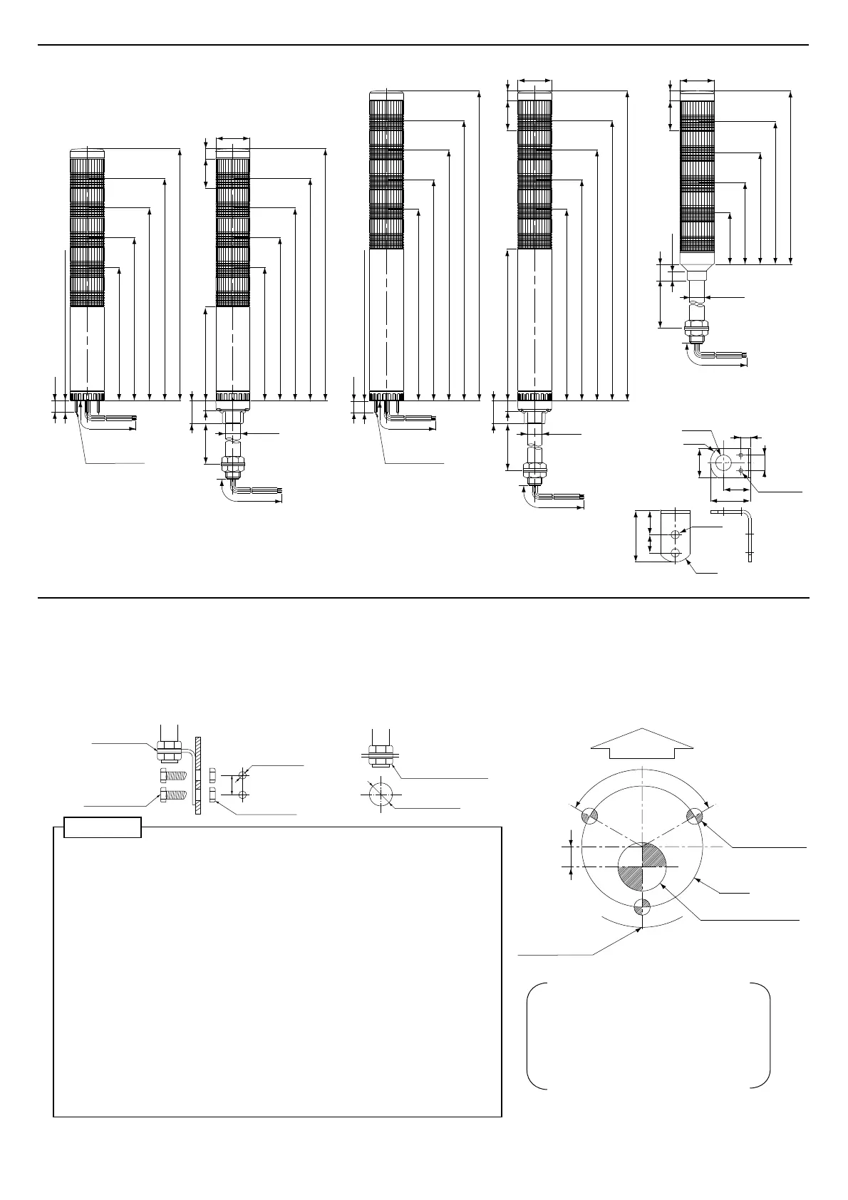
(Unit:mm)
Using this template
1. Confirm the hole position on the product.
2. Secure the template to the installation surface
using adhesive tape.
3. Mark the installation holes using a nail punch,
etc.
4. Drill the holes in the installation surface.
※ Confirm the direction of the name plate and the
wiring route before you drill the holes.
φ30
3-120°
Wiring thru
hole φ12
Installation
hole 3-φ4
5
Name plate
position
Buzzer transmission
direction
5. Installation
[Mounting]
● Drill mounting holes in the wall or panel. (See the following installation diagram.)
● Secure the side mounting bracket with hex bolts and hex nuts (not supplied) .
● Install the Signal Tower vertically at a location that has sufficient strength and minimal vibration.
● With buzzer models, the alarm can be heard best from the front direction.
Therefore, make sure the Signal Tower is facing the correction direction before installation.
● This product can be used only indoors. (Do not use it outdoors.)
● Do not install the Signal Tower sideways or inverted.
● Make sure of the specified operating voltage and current before use.
● Do not leave the product or use it without LED unit installed.
● Use the soft cloth with moisture when the LED unit or bodies must be cleaned
up. (Do not use thinner, benzine, gasoline or oil.)
● When installing this product, do not twist the product with excessive torque or
the product may be damaged.
●
During installation, do not remove the waterproof sheet. It may cause a malfunction.
● This product has 1mm thick waterproof packing at the bottom of the pole
bracket. However, when complete waterproofing is not provided due to the
unevenness of the installation surface, apply waterproof sealant between
the unit and the installation surface to maintain waterproof conditions.
● For use on a flat surface of a Type 1 Enclosure.
●
For the model LCE-□02A(FB)(W), maximum surrounding air temperature is at 40℃.
For the model LCE-□M2A(FB)(W), LCS-□02A, maximum surrounding air
temperature is at 60℃.
※ Warranty is not valid for malfunctions that are caused by handling that does
not observe the caution instructions, unauthorized modifications or natural
calamities. Do not use this product for purposes other than those specified
in this manual.
Caution
Panel board maximum
installable thickness : 10
1400
1100
35
φ40
11
12
111
(13)
1-Light 158
(257.5)
27
φ17.3
5-Lights 298
3-Lights 228
4-Lights 263
2-Lights 193
2-φ9
R20
57
2720
17
11
32
φ17.3
R20
30
44.5
2-φ4.2
(Unit : mm)
4. Dimensions
1350
[LCE-□M2AFB
(
W
)
Type][LCE-□02A
(
FB
)(
W
)
Type / LCE-□M2A
(
W
)
Type]
[Accessory
:L-angle dimension]
1-Light 158
5-Lights 298
3-Lights 228
4-Lights 263
2-Lights 193
950
35
φ40
11
12
167(257.5)
27
φ17.3
1-Light 213
5-Lights 353
3-Lights 283
4-Lights 318
2-Lights 248
[LCE-□□□A
(
FB
)
Type / LCS-□02A Type]
Hex bolt(M8)
Hex nut(M8)
Mounting
bracket
Mounting hole
2-φ9
Flat surface
Hex nut(M17, P=1.5)
Mounting hole
(φ18)
20
●Side Mounting Installation
●Flat Surface Installation
[LCE-□□□A
(
FB
)
W Type]
Panel board maximum
installable thickness : 10
(13)
1150
35
φ40
11
1-Light 61
18
11
(264)
φ17.2
5-Lights 201
4-Lights 166
3-Lights 131
2-Lights 96
[LCS-□02A Type]
1-Light 213
5-Lights 353
3-Lights 283
4-Lights 318
2-Lights 248
3-M3(P=1.5)
3-M3(P=1.5)
 Loading...