pattersonfan.com
800.768.3985
17
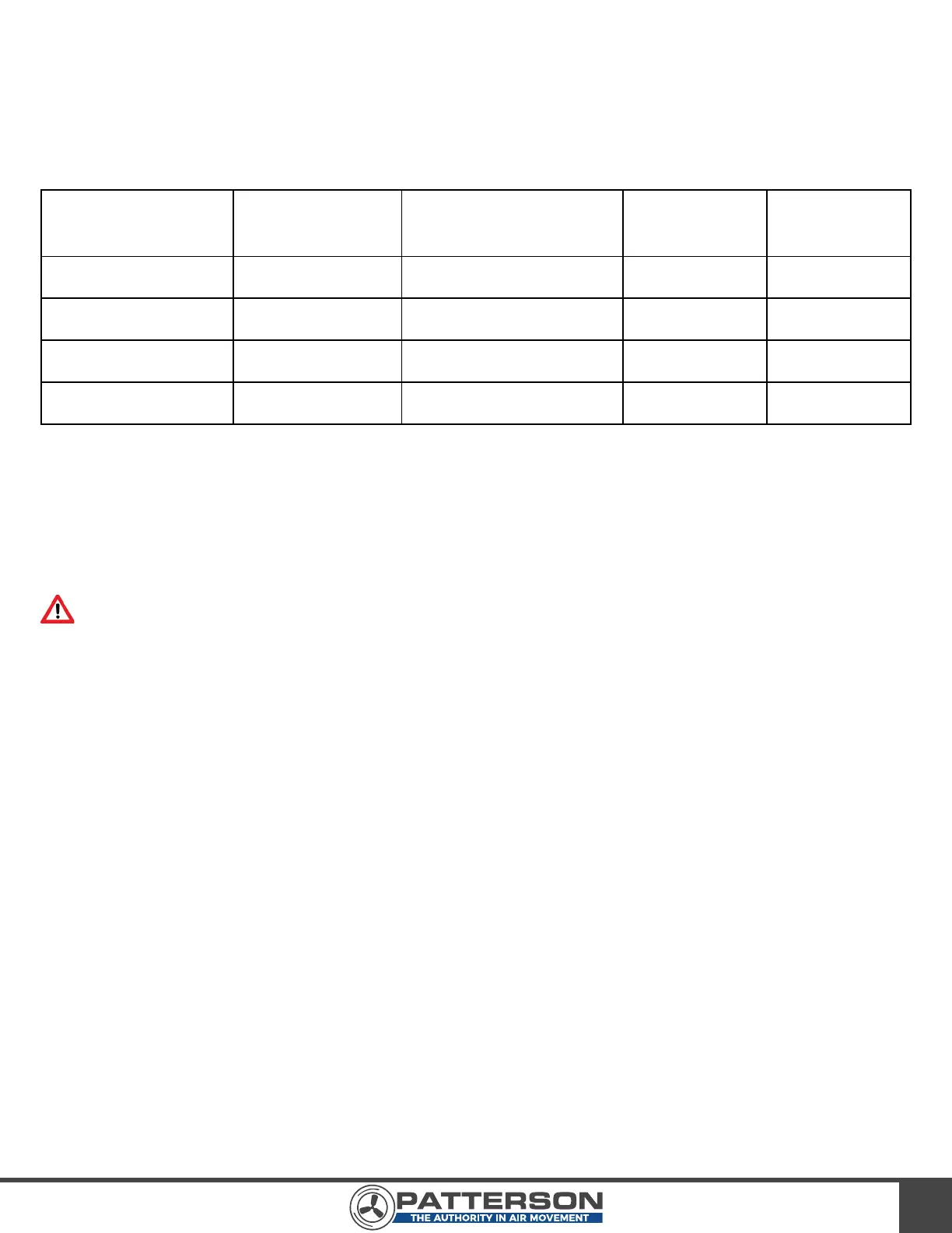
STEP 1 - BREAKER SIZING
1) Refer to Table 1 below for recommended circuit breaker sizing based on input voltage and fan motor
horsepower.
STEP 2 - RUN INPUT POWER CABLE & INSTALL LOCKABLE DISCONNECT
References: Chapter 6 of the ACS355 User’s Manual
WARNING: The Lockable Disconnect must be installed per local electrical
codes. AT MINIMUM it must be installed outside the diameter of the fan
blades.
1) Be sure to size the input power cable properly for the application. Most installations will require
12-gauge wire. However, longer runs of power cable may require 10-gauge or higher.
2) Run input power cable from the power source into the top of the Lockable Disconnect, using the
appropriately sized knockout.
3) Connect conductors to terminals L1, L2, and L3, respectively. Ground wire should be fastened to the
protective earth (PE).
4) Continue running input power to the drive by connecting three conductors to terminals T1, T2, and T3,
respectively. A ground wire should be fastened to the protective earth (PE) provided.
5) Connect the opposite end of the input power cable to the VFD in the manner shown under the
heading “Connecting the Power Cables” in the “ACS355 User’s Manual.” The three conductors
should be connected to U1/L, V1/N, and W1, respectively. The ground wire should be connected in the
manner shown in Image 18.
TABLE 1
Recommended Fuse