pattersonfan.com
800.768.3985
18
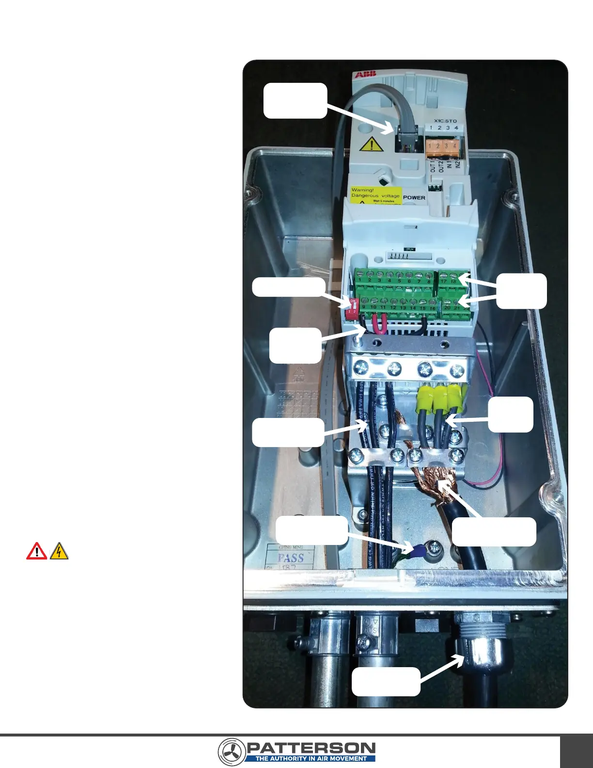
STEP 3 - CONNECT BOTH ENDS OF THE MOTOR CABLE
Reference: Chapter 6 of the ACS355
User’s Manual
1) Remove the cover of the VFD
using a Phillips screwdriver.
2) Pass the cable conductors and
shielding through one of the
provided strain reliefs, and then
through one of the holes on the
bottom of the VFD.
3) Connect one end of the motor
control cable to the VFD in the
manner shown under the heading
“Connecting the Power Cables” in
the “ACS355 User’s Manual.” The
three conductors should be
connected to U2, V2, and W2,
respectively, using the three (3)
yellow wire crimps. The cable foil
shield should be secured by the
cable clamp as shown in Image 18.
4) Connect the opposite end of the
motor control cable to the fan
motor. This will require removal of
one of the knockouts on the
motor’s junction box. As before,
pass the cable conductors and
shielding through the strain relief,
and then through the junction box
hole.
WARNING: The wiring configu-
ration is input voltage dependent.
Please wire the motor properly using
the wiring diagrams found on the fan
motor’s nameplate.
5) Once the cable is properly
connected at both ends, tighten
down the strain reliefs.
6) A successfully wired VFD should
appear like Image 18.
IMAGE 18
Cat 6 Cable
Receptacle
VFD I/O
Terminal
Blocks
Factory
Installed
Jumpers
DIP Switches
Input Voltage
Wiring
Motor
Control
Cable
Input Voltage
Ground Wire
Motor Control
Cable Shielding
Cable Strain
Relief