MODEL BKT WIRE
ASSEMBLY
Continued
Place the blower against the lower rear 3.
wall of the rebox outer wrapper with
the exhaust port directed upward and
the thermodisc position up near the
replace bottom. The thermodisc must
be oriented near the replace bottom
as shown in Figure 6 in order to sense
temperature and properly operate. The
blower will be held in position against the
back wall by the magnets incorporated
onto the blower housing (see Figure 6,
page 4).
Be certain thet all wire terminals are 4.
securely attached to terminals on blower
motor and thermal switch, and that the
screw for the thermodisc bracket and
green ground wire is tight.
To mount speed controls, see 5. Mounting
Speed Control for All Direct Vent Models
(below), Mounting Speed Control for All
Models with Panel Louvers (colum 2) or
Mounting Speed Control for All Models
with Stamped Face Louvers (page 5),
depending on your model.
Page 5
Check to make sure that the power cord 1.
is completely clear of the blower wheel
and that there are no other foreign ob-
jects in blower wheel. Also double check
all wire leads and make sure wire routing
is not pinched or in a precarious position.
Correct accordingly.
CAUTION: Never touch the
blower wheel while in operation.
CONNECTING POWER AND
OPERATING BLOWER
Turn on power to duplex outlet if previ-2.
ously turn off per the warning on page
2.
Plug in blower power cord to duplex 3.
outlet (see Figure 2, page 2).
BK Model: Turn blower on and check 4.
for operation. Turn blower off by turn-
ing knob fully counterclockwise before
continuing.
BKT Model: The blower will only run 5.
when the speed control knob is in the ON
position and the Thermal switch senses
temperature after the replace begins
to heat up. The blower speed can be
adjusted by rotating the control knob. To
turn off, turn knob fully counterclockwise
until it clicks off. If the blower is ON and
has been running with the fireplace
operating, the blower will continue to
run for a short time after the replace
has been turn off. As the thermal switch
cools down, the blower shuts down
automatically.
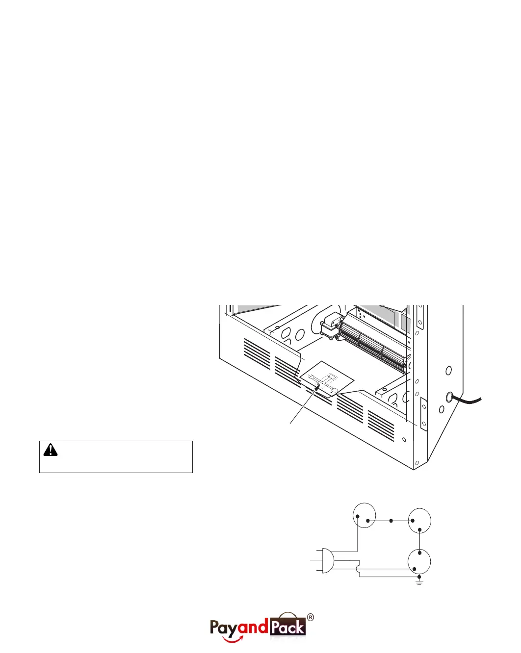
Peel off the backing paper and stick the 6.
supplied wiring diagram decal on the
rebox bottom approximately 12'' in front
of the blower (see Figure 10).
Replace all panels and/or brick bottom 7.
if previously removed.
Figure 10: Location of Wiring Diagram Decal (Model May Vary From Illustration)
Figure 11: Wiring Diagram
Var
iabl
e
Fa
n
Swit
c
h
Whit
e
Whi
te
Bl
ac
k
Green
On
110/115
V.A.C.
Blowe
r
M
ot
or
B
l
ack
B
l
ac
k
Bl
ack
Of
f
Wiring Diagram Decal
12'' in Front of Blower
Red
V a riable
Fan Switch
Fan Switch
(N.O.)
Green
White
On
1 1 0/115
V . A.C.
Blower
Motor
Black
Off
1
2
Black
Blue
(BKT Model Only)
 Loading...