8
PROPERTY DAMAGE HAZARD
Failure to follow this caution may result in product or property
damage.
Shallow running traps are inadequate and DO NOT allow proper
condensate drainage. (See Fig. 17.)
CAUTION
!
DO NOT USE SHALLOW RUNNING TRAPS!
A03013
Fig. 17 − Insufficient Condensate Trap
NOTE: When connecting condensate drain lines, avoid blocking
filter access panel, thus preventing filter removal. After connection,
prime both primary and secondary condensate traps.
NOTE: If unit is located in or above a living space where damage
may result from condensate overflow, a field−supplied, external
condensate pan should be installed underneath the entire unit, and a
secondary condensate line (with appropriate trap) should be run
from the unit into the pan. Any condensate in this external
condensate pan should be drained to a noticeable place. As an
alternative to using an external condensate pan, some localities
may allow the use of a separate 3/4−in (19 mm) condensate line
(with appropriate trap) to a place where the condensate will be
noticeable. The owner of the structure must be informed that when
condensate flows from the secondary drain or external condensate
pan, the unit requires servicing or water damage will occur.
Install traps in the condensate lines as close to the coil as possible.
(See Fig. 16.) Make sure that the outlet of each trap is below its
connection to the condensate pan to prevent condensate from
overflowing the drain pan. Prime all traps, test for leaks, and
insulate traps if located above a living area.
Condensate drain lines should be pitched downward at a minimum
slope of 1−in (25 mm) for every 10−ft (3 m) of length.
Consult local codes for additional restrictions or precautions.
Step 8 — Accessories
A. Electric Heaters
See unit rating plate for factory−approved electric heater kits.
Follow installation instructions provided with kit.
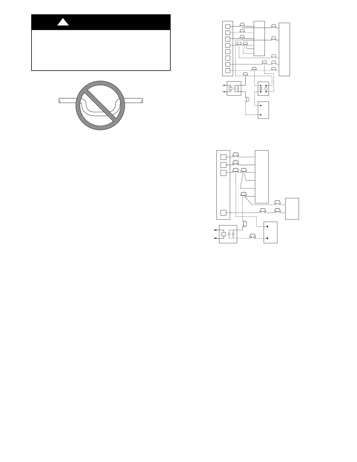
B. Humidifier
Connect humidifier and humidistat to fan coil unit as shown in Fig.
18 and Fig. 19. The cooling lockout relay is optional.
R
G
C
E
L
O
Y
THERMOSTAT
R
R
C
O
Y
G
C
W
2
W
2
W
2
W
3
E
FAN COIL
(CONTROL)
HEAT PUMP
(CONTROL)
RED
GRY
BRN
WHT
WHT
BLU
VIO
HUMIDISTAT
RELAY
FAN HUMIDIFIER
115V
M
A95294
Fig. 18 − Wiring Layout of Humidifier to Heat Pump
R
G
W
Y
THERMOSTAT
R
G
W
2
W
3
E
C
FAN COIL
(CONTROL)
C
Y
AIR COND.
HUMIDISTAT
FAN HUMIDIFIER
115V
RED
GRY
WHT
WHT
BLU
VIO
BRN
M
A95295
Fig. 19 − Wiring Layout of Humidifier to Fan Coil
With Electric Heat
Step 9 — Sequence of Operation
A. Continuous Fan
Thermostat closes R to G. G energizes fan relay on PCB which
completes circuit to indoor blower motor. When G is de−energized,
there is a 90 second delay before relay opens.
NOTE: Speed taps 1, 2 and 3 have a 90 second blower off delay.
Speed taps 4 and 5 have 0 second blower off delay.
B. Cooling Mode
Thermostat energizes R to G, R to Y, and R to O (heat pump only).
G energizes fan relay on PCB which completes circuit to indoor
blower motor. When G is de−energized, there is a 90 second delay
before fan relay opens.
NOTE: Speed taps 1, 2 and 3 have a 90 second blower off delay.
Speed taps 4 and 5 have 0 second blower off delay.