Do you have a question about the PC Chips M755LMR V7.1 and is the answer not in the manual?
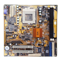
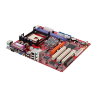
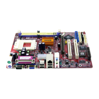
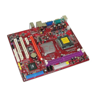
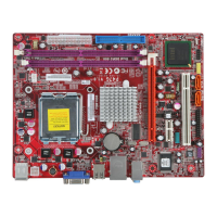
This manual describes a mainboard designed for multimedia workstations and network-ready systems. It supports Socket 370 processors, including PPGA/FCPGA Celeron and FCPGA Pentium III CPUs, with Front Side Bus (FSB) speeds of 66MHz, 100MHz, or 133MHz. The mainboard automatically configures processors using firmware and a synchronous/asynchronous Host/DRAM Clock Scheme.
The mainboard features two 168-pin DIMM slots for SDRAM memory modules, supporting memory bus speeds of 66MHz, 100MHz, and 133MHz. The maximum installed memory is 1GB (2 x 512MB).
It includes two 32-bit PCI slots and one AMR (Audio Modem Riser) slot for a dedicated audio/modem riser card.
The mainboard provides primary and secondary PCI IDE channels, supporting PIO (programmable input/output) modes, Multiword DMA modes, and Bus Mastering and Ultra DMA 33/66 modes.
It is equipped with an AT/ATX power supply connector and supports ACPI and previous PMU (Power Management Unit) features. These include a suspend switch, keyboard power on/off, Wake on Modem, Wake on LAN, and Wake on Alarm.
The integrated graphics system is a 128-bit 2D/3D 100MHz Host interface AGP Graphics Accelerator, compliant with AGP V2.0. It utilizes shared memory architecture, allowing a maximum of 64MB of main memory to act as a frame buffer. It supports high resolutions up to 1920x1200 16M colors and 2048x2048 Texture size with a Virtual screen up to 4096x4096. It also supports hardware DVD acceleration.
The mainboard includes an AC97 2.1 compliant codec with an 18-bit ADC (Analog Digital Converter) and DAC (Digital Analog Converter), as well as an 18-bit stereo full-duplex codec.
It provides PC99 Color Connectors for easy peripheral device connections. It includes a floppy disk drive connector with 1Mb/s transfer rate, one serial port with 16550-compatible fast UART, and one parallel port with ECP and EPP support. An optional ATX form card provides two USB ports, a mini-DIN port for PS/2 mouse, and one mini-DIN port for infrared. An optional extended USB module provides two extra USB ports.
The mainboard features a 10BaseT/100BaseTX Ethernet LAN. The LAN controller integrates Fast Ethernet MAC and PHY, compliant with IEEE802.3U 100BASE-TX, 10BASE-T and ANSI X3.263 TP-PMD standards. It is compliant with ACPI 1.0 and the Network Device Class Power Management 1.0. It offers high performance provided by a 100Mbps clock generator and data recovery circuit for 100Mbps receiver.
The Flash ROM supports automatic CPU and board configuration, as well as Plug and Play configuration of peripheral devices and expansion cards. It includes built-in virus protection using Trend's ChipAwayVirus, which provides boot process virus protection.
The mainboard comes with several software applications:
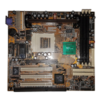
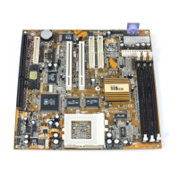
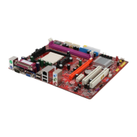
The mainboard has a Baby-AT form factor, measuring 22cm x 22cm.
The M755LMR (LAN/Modem Ready), M755LR (LAN Ready), M755MR (Modem Ready), and M755 models are available. Each model supports different specifications:
The mainboard package typically includes:
Optional accessories that can be purchased include:
Components on the mainboard can be damaged by static electricity. When unpacking and installing the mainboard, users must:
To install the mainboard in a system, follow these procedures:
This mainboard supports Socket 370 processors, specifically PPGA/FCPGA Celeron and FCPGA Pentium III processors. To ensure reliability, ensure the processor has a heatsink/cooling fan assembly. Do not attempt to install a Socket 7 processor in the Socket 370. A Socket 7 processor, such as the Pentium-MMX, or the AMD K5/K6, does not fit in the Socket 370.
The following list notes the processors supported by this mainboard:
A processor installs into the ZIF (Zero Insertion Force) Socket-370 on the mainboard.
The mainboard has two DIMM sockets for system memory modules. At least one memory module must be installed in order to use the mainboard. The first memory module must be installed in the DIMM1 socket to provide shared memory to the onboard VGA display circuitry.
For this mainboard, 168-pin, 3.3V unbuffered SDRAM memory modules must be used. If the installed CPU uses a 100 MHz system bus, PC100/PC133 memory must be used. If the installed CPU uses a 66 MHz system bus, PC66/PC100 memory must be used. The maximum installed memory size is 2 x 512MB = 1 GB. The edge connectors on the memory modules have cut outs, which coincide with spacers in the DIMM sockets so that memory modules can only be installed in the correct orientation.
Jumpers are sets of pins that can be connected together with jumper caps. Jumper caps change the way the mainboard operates by changing the electronic circuits. If a jumper cap connects two pins, they are SHORT. If a jumper cap is removed from two pins, the pins are OPEN.
If this feature is enabled, hot keys on the keyboard can be used as a power on/off switch for the system. The system must provide 1A on the +5VSB (+5V Standby) signal for this function.
This controls the LAN Wake Up feature, where the system will wake up in response to a signal over a LAN. It is connected to WOL1. The system must provide 1A on the +5VSB (+5V Standby) signal for this feature.
This jumper is used to clear the contents of the CMOS memory. This may be needed to clear the CMOS memory settings in the Setup Utility if they are incorrect and prevent the mainboard from operating. To clear the CMOS memory, disconnect all power cables from the mainboard and then move the jumper cap into the CLEAR setting for a few seconds.
The mainboard is a Baby-AT size mainboard with a set of I/O ports. It can be installed in any AT case. Ensure the case has an I/O cover plate that matches the ports on this mainboard. Install the mainboard in a case. Follow the instructions provided by the case manufacturer using the hardware and internal mounting points on the chassis.
Connect the power connector from the power supply to the PWR2/PWR1 AT/ATX Power connector on the mainboard. If there is a cooling fan installed in the system chassis, connect the cable from the cooling fan to the FAN2 fan power connector on the mainboard. Connect the case switches and indicator LEDs to the J2 switch and LED connector header. See the illustration below for a guide to the J2 connector pin assignments.
Extension brackets are used to connect features on the mainboard to external connectors that can be attached to the system chassis. Follow the steps below to install the extension brackets. Note: All ribbon cables used on the extension brackets have a red stripe on the Pin-1 side of the cable.
This bracket provides three audio jacks for stereo line in, stereo line out, and microphone. In addition, it has a 15-pin D-connector which can be used by either a joystick or a MIDI device. If using a four-channel speaker system, channel one and two are output through the Stereo Line-out, and the rear speaker channels three and four are output through Stereo Line-in.
This bracket has one serial port – COM1 (9-pins) and one parallel port – PRN1 (25-pins). On this mainboard, the second serial port is reserved for the Fax/Modem, so only one of the serial ports can be connected to the mainboard header COM1.
The VGA extension bracket has a 15-pin connector for an external monitor cable.
This bracket supports an RJ45 network connector and connects to the built-in LAN header on the mainboard.
For this mainboard, an ATX form card and a USB module extension bracket can be obtained. Install them by following the steps below.
This ATX Form Card provides a mini-DIN port for infrared, one mini-DIN port for a PS/2 mouse. In addition, it has two USB (Universal Serial Bus) ports.
This module bracket has two USB ports for more USB devices.
Install and connect any other devices in the system by following the steps below.
The mainboard ships with a floppy disk drive cable that can support one or two drives. Drives can be 3.5" or 5.25" wide, with capacities of 360K, 720K, 1.2MB, 1.44MB, or 2.88MB. Install drives and connect power from the system power supply. Use the cable provided to connect the drives to the floppy disk drive header FDC1.
IDE devices include hard disk drives, high-density diskette drives, and CD-ROM or DVD-ROM drives, among others. The mainboard ships with an IDE cable that can support one or two IDE devices. If connecting two devices to a single cable, one must be configured as Master and one as Slave. The documentation of the IDE device will tell how to configure the device as a Master or Slave device. The Master device connects to the end of the cable. Install the device(s) and connect power from the system power supply. Use the cable provided to connect the device(s) to the Primary IDE channel connector IDE1 on the mainboard.
If more IDE devices are to be installed, a second IDE cable can be purchased and connected to the Secondary IDE channel connector IDE2 on the mainboard. If two devices are on the cable, one must be Master and one must be Slave.
If a CD-ROM drive or DVD-ROM drive is installed, the drive audio cable can be connected to the onboard sound system. On the mainboard, locate the two 4-pin connectors CD1 and CD2. There are two kinds of connector because different brands of CD-ROM drives have different kinds of audio cable connectors. Connect the cable to the appropriate connector.
If a secondary CD-ROM drive or DVD-ROM drive is installed, its audio cable can be connected to the onboard sound system. On the mainboard, locate the 4-pin Aux-In header AUX1. Connect the cable to the connector.
This mainboard has two 32-bit PCI expansion slots and one AMR slot. Follow the steps below to install a PCI/AMR expansion card.
The AMR (Audio Modem Riser) slot is an industry standard slot that allows for the installation of a special audio/modem riser card. Different territories have different regulations regarding the specifications of a modem card. A card that is approved in your area can be purchased and installed directly into the AMR slot.
If an ATX power supply is used, the system can be configured to resume by alarms. If a LAN adapter expansion card is installed, connect the card to the Wake On LAN connector WOL1. This allows incoming traffic to resume the system from a software power down. This feature needs to be enabled in the system setup utility.
The BIOS Setup Utility records settings and information about the computer, such as the date and time, hardware installed, and various configuration settings. The computer uses this information to initialize all components when booting up and functions as the basis for coordination between system components. If the Setup Utility configuration is incorrect, it may cause the system to malfunction. If this happens, the Clear CMOS jumper can be used to store the configuration information, or the Page Up key can be held down while rebooting to clear the setup information. The setup utility can be run to manually make changes to the configuration. This may be needed to configure some of the hardware that is installed or connected to the mainboard, such as the CPU, system memory, disk drives, etc.
Each time the computer starts, before the operating system loads, a message appears on the screen that prompts to "Hit if you want to run SETUP". When this message appears, press the Delete key to enter the Main menu page of the Setup Utility. The cursor arrow keys can be used to highlight any of the options on the main menu page. Press Enter to select the highlighted option. To leave the Setup Utility, press the Escape key. To cycle through the Setup Utility's optional color schemes, hold down the Shift key and press F2. Some of the options on the main menu page lead to tables of items with installed values. To highlight items, use the cursor arrow keys, and to cycle through the alternate values for each of the items, use the PgUp and PgDn keys. Other options on the main menu page lead to dialog boxes which require a Yes or No answer by hitting the Y or N keys. If changes have already been made to the setup utility, press F10 to save these changes and exit the utility. Press F5 to reset the changes to the original values. Press F6 to install the setup utility with a set of default values. Press F7 to install the setup utility with a set of high-performance values.
This page sets some of the parameters for the hardware monitoring function of this mainboard.
This page sets more advanced information about the system. Making changes can affect the operation of the computer.
This page sets some of the parameters for system power management operation.
This page sets some of the parameters for devices installed on the PCI bus and devices that use the system plug and play capability.
If this item is selected and Enter is pressed, a dialog box appears. If Y is pressed and Enter is pressed, the Setup Utility loads a set of fail-safe default values. These default values are not very demanding and should allow the system to function with most kinds of hardware and memory chips.
If this item is selected and Enter is pressed, a dialog box appears. If Y is pressed and Enter is pressed, the Setup Utility loads a set of best-performance default values. These default values are quite demanding and the system might not function properly if slower memory chips or other low-performance components are used.
This page sets some of the parameters for peripheral devices connected to the system.
This page automatically configures the mainboard for the CPU. The system will automatically detect the kind of CPU that is installed and make the appropriate adjustments. If the wrong speed and the system doesn't run properly, press the Page Up key while the system is booting to restore the incorrect CPU setting.
This page sets some of the parameters for the hardware monitoring function of this mainboard.
If this item is highlighted and Enter is pressed, a dialog box appears which lets a Supervisor password be entered. A password can be up to six letters or numbers. Press Enter after typing in the password. A second dialog box asks to retype the password for confirmation. Press Enter after retyping it correctly. The password is then required to access the Setup Utility or for that and at start-up, depending on the setting of the Password Check item in Advanced Setup.
Highlight this item, press Enter, and type in the current password. At the next dialog box, type in the new password, or just press Enter to disable password protection.
Highlight this item and press Enter to save the changes that have been made in the Setup Utility configuration and exit the program. When the Save and Exit dialog box appears, press Y to save and exit, or press N to exit without saving.
The support software CD-ROM is included in the mainboard package and contains all the drivers and utility programs needed to properly run the products. Below is a brief description of each software program, and the location for its mainboard version. More information on some programs is available in a README file located in the same directory as the software. If the operating system used in the system is Windows 98, all drivers and utilities will automatically install. See the Auto-Installing under Windows 98 section.
The software on the support CD-ROM is for Windows 95/NT/2000 and Windows 98. The installation procedure differs depending on which Operating System is used, but the automatic installation is for Win98 only.
To install support software for Windows 95/NT/2000, follow these general procedures:
Note: The correct path name for each software driver is provided, where D: identifies the CD-ROM drive letter – modify if necessary.
The IDE Bus Master Drivers allows the system to properly manage the IDE channels on the mainboard. Only need to install an IDE driver if running Windows 95. Use the default Windows driver on the Windows CD-ROM disc.
Find the display drivers and software here:
The audio driver allows the system to use the onboard audio circuitry. Find the driver and audio application here:
Find the network interface driver here:
Find the fast-modem drivers and software here:
The USB driver allows the system to recognize the USB ports on the mainboard. This driver only needs to be installed if running Windows 95. Windows 95 OSR2 does not require this driver. This driver is available for:
Find the software here:
The BIOS Update utility allows updating the BIOS file on the mainboard to a newer version. The latest version of the BIOS setup available for the mainboard can be downloaded from the website.
The PC-cillin software program provides anti-virus protection for the system. Find this program here:
The support software CD-ROM disc loads automatically under Windows 98. When the CD-ROM disc is inserted, the AutoRun feature will automatically bring up the install screen. The screen has three buttons: on it, Setup, Browse CD, and Exit. See the following screen illustration. When the Setup button is clicked, the software installation program will run, and the kind of installation can be selected. This is explained later in this section. The Browse CD button is the standard Windows command that allows examining the contents of the disc using the Windows 98 file browsing interface. The Exit button closes the Auto Setup window. To run the program again, reinsert the CD-ROM disc or click on AutoRun in the context sensitive menu for the CD-ROM drive icon in a file browser window.
To install support software for the system board, follow this procedure:
| Brand | PC Chips |
|---|---|
| Model | M755LMR V7.1 |
| Category | Motherboard |
| Language | English |