This document provides information about a mainboard, including its features, installation procedures, BIOS setup utility, and bundled software.
The publication is protected by international copyright laws, and no part of the manual or its contents may be reproduced without the manufacturer's written consent. The information is subject to change without notice, and the manufacturer disclaims any warranties regarding the contents. The manufacturer reserves the right to revise the publication and make changes without obligation to notify any person of such revisions.
Trademarks:
- IBM, VGA, and PS/2 are registered trademarks of International Business Machines.
- AMD, Duron, and Athlon are registered trademarks of Advanced Micro Devices Inc.
- Microsoft, MS-DOS, and Windows 98/ME/NT/2000/XP are registered trademarks of Microsoft Corporation.
- PC-cillin is a registered trademark of Trend Micro Inc.
- AMI is a registered trademark of American Megatrends Inc.
- A3D is a registered trademark of Aureal Inc.
- MediaRing Talk is a registered trademark of MediaRing Inc.
- 3Deep is a registered trademark of E-Color Inc.
- Other names used in this publication may be trademarks and are acknowledged.
Copyright: © 2003, All Rights Reserved. M825 Series, V7.2A, VKM266/May 2003.
Notice Regarding Drivers
Due to varying Microsoft certification schedules, some drivers might not yet be certified by Microsoft. If a "Windows Logo testing" warning appears during installation under Windows XP, rest assured that the R&D department has tested and verified these drivers. Users should click "Continue Anyway" to proceed with the installation.
USB 2.0 Driver Limitations:
- The USB 2.0 driver supports only Windows XP and Windows 2000.
- Connecting a USB 2.0 hub to the root hub and then plugging USB devices into it might prevent the system from recognizing these devices.
- A solution for these limitations is being developed and will be released on www.pcchips.com.tw.
Chapter 1: Introduction
This mainboard supports Socket-A for AMD K7 processors with a 266MHz front-side bus speed.
Chipset:
- Features a KM266 Northbridge and VT8235 Southbridge.
- Supports one 4X AGP slot for high-graphics display.
- Supports 100/133 MHz DDR and Ultra DMA ATA100/133 for high system performance.
- Includes a built-in AC97 Codec, a CNR (Communications and Networking Riser) slot, and a 10BaseT/100BaseTX Network Interface.
- Integrated 128-bit 2D/3D AGP Graphics Accelerator with 32MB frame buffer, supporting AGP 4X 266MHz mode up to 1GB/s bandwidth. This provides a direct connection between the graphics subsystem and memory, reducing competition for processor time on the PCI bus.
- Full set of I/O Ports: PS/2 keyboard and mouse, one serial port, one onboard VGA (S3) port, one parallel port, and up to six USB2.0 ports (four back-panel, two via onboard USB header USB3 for an Extended USB Module).
- Micro ATX size with power connectors for an ATX power supply.
Key Features
Socket-A Processor Support:
- Supports AMD Athlon XP/Athlon/Duron processors.
- Supports 266 MHz Front-Side Bus.
Chipset (VIA KM266 Northbridge and VT8235 Southbridge):
- Advanced V-Link memory controller architecture: up to 266 MB/s bandwidth, optimized for demanding Internet and 2D/3D graphics.
- 4xAGP interface support: vivid 2D/3D graphics and video performance.
Memory Support:
- Two 184-pin DIMM slots for DDR memory modules.
- Supports 100/133 MHz memory bus.
- Maximum installed memory: 2GB.
Expansion Slots:
- One CNR slot.
- One 4X AGP slot for AGP 2.0-compliant interface.
- Two 32-bit PCI slots for PCI 2.2-compliant bus interface.
Onboard IDE channels:
- Primary and Secondary PCI IDE channels.
- Supports PIO (programmable input/output) modes.
- Supports Multiword DMA modes.
- Supports Bus Mastering and Ultra DMA ATA 100/33/66/100/133 modes.
Power Supply and Power Management:
- ATX power supply connector.
- ACPI and previous PMU support, suspend switch, keyboard power on/off.
- Supports Wake on LAN.
VGA:
- Single cycle 128-bit 3D architecture.
- 128-bit 2D graphic engine.
- 8/16/32 MB frame buffer using system memory.
- Supports AGP 4X 266 MHz mode up to 1GB/s bandwidth.
- Supports 250MHz RAMDAC.
- 2D/3D resolutions up to 1920x1440.
- Supports AGP Rev. 2.0 Spec. Compliant.
AC97 Codec:
- Compliant with AC'97 2.1 specification.
- 16-bit stereo full-duplex CODEC with fixed 48KHz sampling rate.
- 3 analog line-level stereo inputs with 5-bit volume control: LINE-IN, CD-IN.
- Three Audio Jacks: Line-Out, Line-In, and Microphone-In.
- Sound Blaster, Sound Blaster Pro Compatible.
- Advanced power management support.
Onboard I/O Ports:
- Provides PC99 Color Connectors for easy peripheral device connections.
- Floppy disk drive connector with 1Mb/s transfer rate.
- Two PS/2 ports for keyboard and mouse.
- One serial port with 16C550-compatible fast UART.
- One parallel port with ECP and EPP support.
- One VGA port.
- Four back-panel USB2.0 ports and extra two USB2.0 ports (onboard USB header USB3).
- One infrared port connector for optional module.
Built-in Ethernet LAN (optional):
- 10Base-T/100Base-TX Physical Layer Solution.
- Dual Speed - 100/10 Mbps.
- MII Interface to Ethernet Controller/Configuration & Status.
- Auto Negotiation: 10/100, Full/Half Duplex.
- Meets All Applicable IEEE802.3, 10Base-T and 100Base-TX Standards.
USB 2.0:
- Compliant with Universal Serial Bus Specification Revision 2.0.
- Compliant with Intel's Enhanced Host Controller Interface Specification Revision 0.95.
- Compliant with Universal Host Controller Interface Specification Revision 1.1.
- PCI multi-function device: two UHCI Host Controller cores for full-/low-speed signaling and one EHCI Host Controller core for high-speed signaling.
- Root hub: 4 downstream facing ports with integrated physical layer transceivers shared by UHCI and EHCI Host Controller.
- Supports PCI-Bus Power Management Interface Specification release 1.1.
- Legacy support for all downstream facing ports.
Hardware Monitoring:
- Built-in hardware monitoring for CPU & System temperatures, fan speeds, and mainboard voltages.
Onboard Flash ROM:
- Supports Plug and Play configuration of peripheral devices and expansion cards.
Bundled Software:
- PC-Cillin2002: automatic virus protection under Windows 98/ME/NT/2000/XP.
- MediaRing Talk: PC to PC or PC to Phone internet phone communication.
- 3Deep: precise imagery and accurate color display on monitor.
- PC DJ: dual-MP3 player for mixing music.
- Adobe Acrobat Reader V5.0: for reading .PDF files.
Dimensions:
- Micro ATX form factor (24.4cm x 19cm).
Package Contents
Attention: This mainboard series has two models: M825LU (USB2.0, LAN) and M825U (USB2.0). Contact your local supplier for model-specific information.
- M825LU: Onboard LAN PHY chip (U11), supports USB2.0 + RJ-45 LAN connector.
- M825U: Supports USB2.0 connector only.
Standard Package Items:
- The mainboard.
- The User's Manual.
- One diskette drive ribbon cable (optional).
- One IDE drive ribbon cable.
- Software support CD.
Optional Accessories (purchasable separately):
- Extended USB module.
- Card Reader (contact your local Card Reader vendor for specification and compatibility issues).
Static Electricity Precautions
Components on this mainboard can be damaged by static electricity.
- Keep components in original static-proof packaging until installation.
- During installation, wear a grounded wrist strap or discharge static electricity by touching the system chassis's bare metal.
- Handle the mainboard by its edges; avoid touching components unless necessary.
- Place the mainboard on its static-protection packaging with the component side facing up during installation.
Pre-Installation Inspection
- Inspect the mainboard for damage to components and connectors.
- If damage is suspected, do not connect power; contact your vendor.
Chapter 2: Mainboard Installation
Installation Steps:
- Identify mainboard components.
- Install a CPU.
- Install memory modules.
- Ensure all jumpers and switches are set correctly.
- Install the mainboard in a system chassis.
- Connect extension brackets or cables to mainboard headers.
- Install other devices and make connections to mainboard headers.
Note:
- Before installation, ensure jumper JP2 is set to Normal.
- Never connect power during installation to prevent damage.
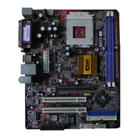
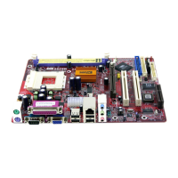
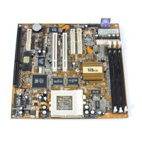
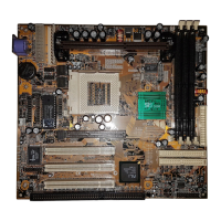
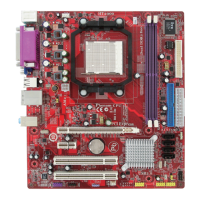
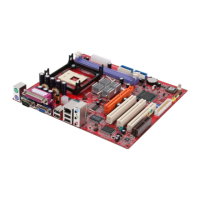
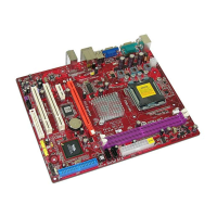
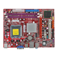
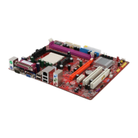
Mainboard Components (Diagram provided)
I/O Ports (Side View Diagram provided):
- PS/2 Mouse: Upper PS/2 port for pointing device.
- PS/2 Keyboard: Lower PS/2 port for keyboard.
- LPT1: Parallel port for printers or other parallel communication devices.
- COM1: Serial port for mice or fax/modems.
- VGA: VGA port for VGA devices.
- LAN Port (optional): RJ-45 jack for network connection.
- USB Ports: For USB devices. (Note: Lower USB port near VGA is shared with READER1 connector).
- Audio Ports: Three audio jacks: stereo Line-In, stereo Line-Out, and Microphone.
Installing the Processor
This mainboard has a Socket 462 processor socket. Choose a processor based on system performance requirements, considering design, clock speed, system bus frequency, and cache memory.
CPU Installation Procedure:
- Unhook and raise the CPU socket's locking lever.
- Match pin 1 corner of CPU socket to processor and insert the processor without force.
- Push the locking lever down and hook it under the latch.
- Apply thermal grease to the CPU top.
- Lower the CPU fan/heatsink unit onto the CPU and socket, snapping retention module clamps into place.
- Plug the CPU fan power cable into CPUFAN1 on the mainboard.
Install Memory Modules
- Accommodates two 184-pin 2.5V unbuffered Double Data Rate SDRAM (DDR SDRAM) DIMM sockets.
- Supports up to 2.0 GB of 200/266 MHz DDR SDRAM.
- DDR SDRAM: supports data transfers on both edges of each clock cycle (rising and falling), doubling data throughput.
- DDR DIMMs: synchronously work with 100 MHz or 133 MHz memory bus.
- Data transfer rate: 1.6 GB/s or 2.1 GB/s (depending on 100 MHz or 133 MHz bus).
- Requires 184-pin 2.5V unbuffered DIMM module.
Installation Procedure:
- Push down latches on each side of DIMM socket.
- Align memory module with socket (keyed with notches and cutouts).
- Check cutouts on DIMM module edge connector match notches in DIMM socket.
- Install DIMM module firmly until latches lever up and latch onto edges.
- Install any remaining DIMM modules.
Jumper Settings
Jumpers are sets of pins connected by jumper caps, altering mainboard operation. SHORT means two pins are connected; OPEN means no jumper cap.
Jumper JP2: Clear CMOS Memory:
- Clears CMOS memory if Setup Utility settings are incorrect or prevent operation.
- To clear: disconnect power, move jumper cap to CLEAR setting for a few seconds.
- Function / Jumper Setting:
- Normal / Short Pins 1-2
- Clear CMOS / Short Pins 2-3
Jumper JP3: CPU Clock Selector:
- 3-pin jumper selects processor 133 MHz or 100 MHz.
- Function / Jumper Setting:
- 100 MHz / Short Pins 1-2
- 133 MHz / Short Pins 2-3
Install the Mainboard
- Install in a system chassis (case). Micro ATX size, fits ATX cases.
- Ensure case has an I/O cover plate matching mainboard ports.
- Follow case manufacturer instructions for hardware and mounting points.
- Connect power connector from power supply to ATX1 connector (CPUPW1 is CPU Vcore power connector).
- If a cooling fan is installed, connect its cable to SYSFAN1 fan power connector.
- Connect case switches and indicator LEDs to PANEL1 header.
- PANEL1 Pinout:
- 1: HDD LED P / 2: PWR/ACPI LED
- 3: HDD LED N / 4: PWR/ACPI LED
- 5: RESET / 6: POWER BUTTON
- 7: RESET / 8: POWER BUTTON
- 9: NC / 10: KEY
Connecting Optional Devices
SPK1: Speaker Connector:
- Connect PC speaker cable to SPK1 header.
- SPK1 Pinout:
- 1: +5V / 2: NC
- 3: GND / 4: SPKR
AUDIO2: Front Panel Audio Header:
- For auxiliary front-oriented microphone and line-out ports.
- AUDIO2 Pinout:
- 1: AUD MIC / 2: AUD GND
- 3: AUD MIC BIAS / 4: AUD VCC
- 5: AUD FPOUT R / 6: AUD RET R
- 7: HP ON / 8: KEY
- 9: AUD FPOUT L / 10: AUD RET L
- Note: To connect front panel sound jack, remove jumper caps from Pin(5-6) and Pin(9-10) on AUDIO2 header.
USB3: Front panel USB Connector:
- For front-mounted USB ports on computer cases.
- USB3 Pinout:
- 1: VERG FP USBPWR0 / 2: VERG FP USBPWRO
- 3: USB FP P0- / 4: USB FP P1-
- 5: USB FP P0+ / 6: USB FP P1+
- 7: GROUND / 8: GROUND
- 9: KEY / 10: NC
- Installation:
- Locate USB3 header.
- Plug bracket cable onto USB3 header.
- Remove slot cover, install extension bracket, and secure with a screw.
READER1: USB Card Reader Connector (optional):
- For connecting internal USB card reader to read/transfer files and digital images.
- READER1 Pinout:
- 1: STANDBY 5V / 2: USB-
- 3: USB+ / 4: GND
- 5: KEY
- Note: READER1 is shared with the lower USB port beside the VGA port on the I/O back panel.
- Caution: Check pin assignment of cable and USB header before plugging in to avoid damage. Vendor not responsible for incidental/consequential damage from incorrect usage.
SIR1: Infrared Port:
- Allows wireless exchange of information with similarly equipped devices (printers, laptops, PDAs).
- SIR1 Pinout:
- 1: NC / 2: KEY
- 3: +5V / 4: GND
- 5: IRTX / 6: IRRX
- Installation:
- Locate SIR1 header.
- Connect ribbon cable from infrared port to SIR1 header.
- Secure port to system chassis.
Install Other Devices
Floppy Disk Drive:
- Mainboard ships with a floppy disk drive cable supporting one or two 3.5" or 5.25" drives (360K, 720K, 1.2MB, 1.44MB, 2.88MB).
- Install drives, connect power, and use cable to connect drives to FDC1 connector.
IDE Devices:
- Includes hard disk drives, high-density diskette drives, CD-ROM, DVD-ROM drives.
- Mainboard ships with an IDE cable supporting one or two devices.
- If two devices are connected, configure one as Master and one as Slave (Master connects to cable end). Refer to IDE device documentation for configuration.
- Install devices, connect power, and use cable to connect to Primary IDE channel connector IDE1.
- For more IDE devices, purchase a second IDE cable and connect to Secondary IDE channel connector IDE2.
Internal Sound Connections:
- If a CD-ROM or DVD-ROM drive is installed, connect its audio cable to the onboard sound system.
- BIOS should auto-detect CD-ROM/DVD drive. If not, configure in Setup Utility.
- Locate 4-pin connector CD2 on mainboard.
- CD2 Pinout:
- 1: CD IN L / 2: GND
- 3: GND / 4: CD IN R
Expansion Slots
This mainboard has one AGP, one CNR, and two 32-bit PCI slots.
Installation Procedure for PCI/AGP/CNR Expansion Card:
- Locate CNR, AGP, or PCI slots.
- Remove blanking plate from slot.
- Install edge connector of expansion card into slot, ensuring it's seated correctly.
- Secure metal bracket of card to chassis with a screw.
Chapter 3: BIOS Setup Utility
Introduction:
- BIOS Setup Utility records computer settings (date, time, hardware type, configuration).
- Information initializes components during boot and coordinates system functions.
- Incorrect configuration can cause malfunction or prevent booting.
- To clear CMOS memory: use clear CMOS jumper or hold Page Up key during reboot.
- Users can manually change configuration for CPU, system memory, disk drives, etc.
Running the Setup Utility:
- During startup, a message "Hit
if you want to run SETUP" appears. Press Delete key.
- Main menu page of Setup Utility appears.
- Navigation:
- Cursor arrow keys: highlight options.
- Enter: select highlighted option.
- Escape: leave setup utility.
- Shift + F2: cycle through color schemes.
- PgUp / PgDn: cycle through alternate values in tables.
- Y / N: answer dialog box questions.
- F10: save changes and exit.
- F5: reset to original values.
- F6: install default values.
- F7: install high-performance values.
Standard CMOS Setup Page:
- Sets basic information: date, time, IDE devices, diskette drives.
- F3 key: auto-detect and configure hard disks on IDE channels.
- Items:
- Date & Time: Set system date and time.
- Pri Master, Pri Slave, Sec Master, Sec Slave: Configure IDE devices.
- Choose "Auto" for auto-detection.
- If auto-detection fails, set to "User" and manually enter characteristics (Size, Cyls).
- Select "CDROM" for CD-ROM drives.
- Select "Floptical" for ATAPI devices with removable media (ZIP, LS-120).
- Floppy Drive A, Floppy Drive B: Set size and capacity of installed floppy diskette drive(s).
Advanced Setup Page:
- Sets more advanced system information. Changes can affect computer operation.
- Items:
- Quick Boot: Enables faster startup by eliminating some power-on test routines.
- 1st Boot Device, 2nd Boot Device, 3rd Boot Device: Determine device order for loading operating system.
- Try Other Boot Devices: If enabled, searches other boot devices if OS not found in first two locations.
- S.M.A.R.T. for Hard Disks: Enable if IDE hard disks support S.M.A.R.T. (Self-Monitoring, Analysis and Reporting Technology).
- BootUp Num-Lock: Determines if Num Lock key is active/inactive at startup.
- Floppy Drive Swap: If two diskette drives are installed, enables swapping drive A and B.
- Floppy Drive Seek: If enabled, system checks all floppy disk drives at startup. Disable unless using an old 360KB drive.
- Password Check: Determines if password is required for Setup Utility (Setup) or both startup and Setup Utility (Always).
- Boot to OS/2 > 64MB: Enable if booting OS/2 and more than 64MB system memory.
- L2 Cache: Leave enabled as processors on this board have internal cache memory.
- System BIOS Cacheable: If enabled, a segment of system BIOS is cached to main memory for faster execution.
- DRAM Timing by SPD: Enables/disables SDRAM timing defined by Serial Presence Detect.
- DRAM CAS# Latency: Determines SDRAM memory CAS operation. Recommend default value. 2T setting requires faster memory.
- DRAM Bank Interleave: Increases SDRAM memory speed by setting separate memory banks for odd/even addresses, allowing access to upcoming byte while refreshing current byte.
- AGP Mode: OnBoard VGA mode with 1, 2, or 4 multiplied frequency options.
- AGP Comp. Driving: Signals auto or manual driving current on AGP cards. Recommend default value.
- Manual AGP Comp. Driving: Decides AGP current driving value when AGP Driving is set to Manual.
- AGP Aperture Size: Determines effective size of AGP Graphic Aperture where memory-mapped graphic data structures are located.
- CLK Gen Spread Spectrum: Enables clock to generate spread spectrum.
- Auto Detect DIMM/PCI Clk: If enabled, BIOS disables clock signal of free DIMM/PCI slots.
Power Management Setup Page:
- Sets parameters for system power management.
- Items:
- ACPI Aware O/S: Supports ACPI (Advanced Configuration and Power Management Interface). Enable/disable ACPI feature.
- Power Management: Enables/disables power management scheme. Options for power management operation. Both APM and ACPI supported.
- Hard Disk Time Out: Sets timeout to power down hard disk drive if inactive.
- Suspend Time Out (Minute): Sets timeout (minutes) for Suspend mode if system inactive.
- LAN/Ring Power On: System can be turned off with software command. If enabled, system resumes on incoming modem call. Requires ATX power supply.
- Keyboard Power On: If enabled, system resumes by pressing hot keys or typing password. Requires Keyboard Power On jumper and ATX power supply.
- PowerOn by RTC Alarm / Date / Hour / Minute / Second: System can be turned off with software command. If enabled, system resumes at a fixed time based on RTC. Set date/time for wake-up alarm. Requires ATX power supply.
PCI / Plug and Play Setup Page:
- Sets parameters for devices on PCI bus and using system plug and play.
- Items:
- Plug and Play Aware O/S: Enable if using O/S supporting Plug and Play (Windows 95/98).
- Share Memory Size: Allocate main memory for onboard VGA display (8/16/32MB options).
- Primary Graphics Adapter: Indicates if primary graphics adapter uses PCI or AGP bus. Default PCI setting allows onboard display and a second PCI slot display card.
- Allocate IRQ to PCI VGA: If enabled, an IRQ is assigned to PCI VGA graphics system. Set to No to free up an IRQ.
- PCI IDE BusMaster: Enables/disables DMA under DOS mode. Recommend default value.
Load Optimal Settings:
- Loads fail-safe default values. These are not demanding and allow system to function with most hardware/memory chips.
- Highly recommended for best performance.
Load Best Performance Settings:
- Loads best-performance default values. These are demanding and may cause malfunction with slower memory chips or low-performance components.
Features Setup Page:
- Sets parameters for peripheral devices.
- Items:
- OnBoard FDC: Enables/disables onboard floppy disk drive interface.
- OnBoard Serial PortA: Enables/disables onboard COM1 serial port and assigns address.
- OnBoard IR Port: Enables/disables Infrared port and assigns address. Five sub-items determine IR port operation.
- Onboard Parallel Port: Enables/disables onboard LPT1 parallel port and assigns address. Auto setting detects available address.
- Parallel Port Mode: Decides parallel port mode: SPP (Standard Parallel Port), ECP (Extended Capabilities Port), EPP (Enhanced Parallel Port), or ECP + EPP.
- Parallel Port IRQ: Assigns IRQ 5 or 7 to parallel port.
- Parallel Port DMA: Assigns DMA channel to parallel port (0, 1, 3 options).
- OnBoard IDE: Enables/disables either or both onboard Primary and Secondary IDE channels.
- Ethernet Device: Enables/disables onboard Ethernet LAN.
- Audio Device: Enables/disables onboard AC'97 audio chip.
- Modem Device: Enables/disables onboard AC'97 modem chip.
- USB Controller: Enables/disables USB ports.
- USB Device Legacy Support: Enables USB device if installed on system board.
- ThumbDrive Support for DOS: Enables small portion of memory storage device for USB ports.
CPU PnP Setup Page:
- Manually configures mainboard for CPU. System auto-detects CPU type.
- Items:
- CPU Brand/Type: Displays CPU brand and type.
- CPU / DRAM Frequency: Decides frequency of CPU/SDRAM.
Hardware Monitor Page:
- Sets parameters for hardware monitoring.
- Items:
- System / CPU Temperature: Displays CPU and system temperature.
- FANs & Voltage Measurements: Indicates cooling fan speeds (RPM) and system voltage measurements.
Change Password:
- Enter Supervisor password (max six letters/numbers).
- Retype for confirmation.
- Password required for Setup Utility or startup (depending on Password Check setting in Advanced Setup).
Change or Remove the Password:
- Highlight, press Enter, type current password.
- At next dialog, type new password or press Enter to disable protection.
Exit:
- Highlight, press Enter to save changes and exit.
- Dialog box: press Y to save and exit, N to exit without saving.
Chapter 4: Software & Applications
Introduction:
- Support CD-ROM contains useful software, drivers, and utilities.
- More information in README file.
- Insert CD-ROM: Auto Setup screen pops up.
- Windows 98/ME/2000/XP: Auto-installs drivers and utilities.
- Windows NT or Manual Installation: Follow specific instructions.
Installing Support Software:
- Insert support CD-ROM.
- Auto Setup screen displays.
- Screen shows "Setup," "Browse CD," "Exit" (right side) and "Setup," "Application," "ReadMe" (bottom).
- Setup: Runs auto-installing program.
- Browse CD: Standard Windows command to check disc contents.
- Exit: Closes Auto Setup window. Reinsert CD or click CD-ROM driver in Windows Explorer and Setup icon to rerun.
- Application: Brings up software menu for bundled software.
- ReadMe: Leads to Install Path for software driver names.
Auto-installing under Windows 98/ME/2000/XP:
- Click "Setup" button.
- Installation program loads, displays screen. Click "Next."
- Select items to setup (default recommended). Click "Next."
- Support software installs automatically. Follow onscreen instructions, confirm commands, allow computer restarts.
Installing under Windows NT or Manual Installation:
- Click "ReadMe," then "Install Path."
- Find mainboard model name, click to get correct driver directory.
- Install each software according to corresponding driver path.
Bundled Software Information:
- Click "Application" button on Auto Setup screen.
- Software menu appears. Click desired software.
- Follow onscreen instructions to install.