General operation
The amplifier mixes and amplifies the microphone, line, digital and outreach input signals
and feeds them through its sophisticated automatic gain control (AGC) circuitry before
outputting them to the induction loop.
OVERVIEW OF THE PDA103 INDUCTION LOOP AMPLIFIER
4 of 12
3*
9
10
11
12
4
2
1
8
7
5 6
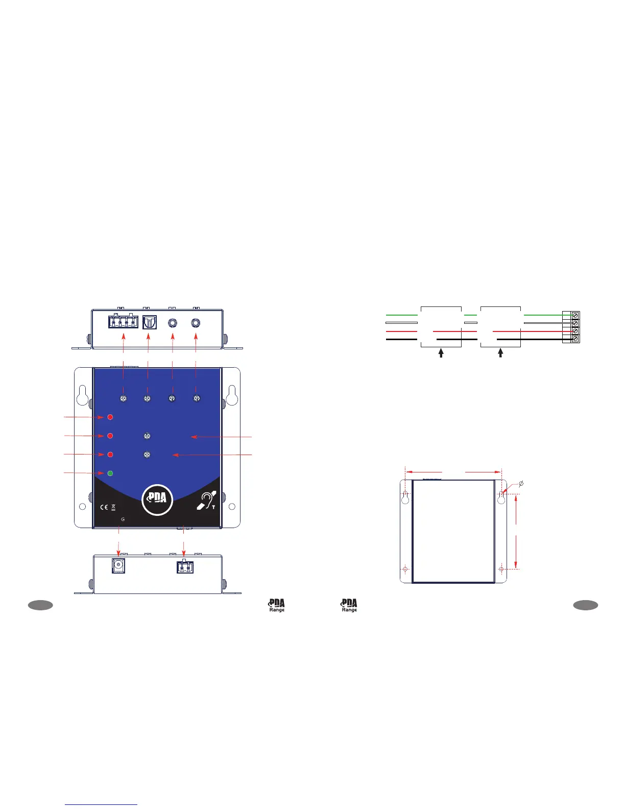
Connectors, controls and indicators
Below is a overview of the PDA103’s connectors, pot level controls and LED indicators.
PDA103 Installation Instructions Approved Document No. DAU0000103 Rev 2
*
T
he
digit
a
l c
onne
c
t
or
a
nd digit
a
l le
v
e
l c
ont
r
ol s
how
n be
low
only
a
pplie
s
t
o t
he
a
mplif
ie
r
s
upplie
d w
it
h t
he
P
D
A
1
0
3
S
k
it
w
hic
h ha
s
a
T
O
S
-link
c
onne
c
t
or
.
OVERVIEW OF THE OUTREACH PLATE AUDIO EXTENSION SYSTEM
The PDA103 is fully compatible with the outreach plate audio input extension system. This
system allows the connection of multiple microphone, or line level inputs via a range of
specially designed wall, ceiling or desk-mountable single gang plates.
Up to ten outreach plates (any mix) can be daisychained to the amplifier’s ‘outreach’
connector (supplied) with cable lengths up to 100m (total network length) easily achievable
using standard two pair audio cable such as Belden 8723 - see typical wiring diagram below.
Contact your supplier for more information.
9 of 12
MOUNTING THE AMPLIFIER
The amplifier can be surface-mounted in any orientation, provided the controls are accessible
and indicators clearly visible.
Surface-mounting
Using mounting screws (not supplied) fix the amplifier securely to the chosen wall, desk or
side of counter, as appropriate. Always assess the condition and construction of the
mounting surface prior to installation and use suitable screw fixings (No. 8-10, or 4-5mm
screws).
PDA103 Installation Instructions Approved Document No. DAU0000103 Rev 2