PDA Pro-Range Instructions • Approved Doc. No. DCP0003168 Rev 1 • Page 15
Compressor: Gives dynamically variable compression ratio from 1:1 (no compression) to 17:1 when both
compression LEDs are lit. In normal use, with the first compression LED lit for part of the time, the
compressor has a “soft knee” characteristic and provides a small degree of compression for signals which
only just light the first LED but a large degree of compression for louder peaks.
Attack time: Approx. 10mS. Release time: Approx. 2.2S
Metal Compensation: True 3dB /octave design counteracts frequency dependent absorption by metal in
the proximity of the installation over a bandwidth of approximately 100Hz – 10KHz.
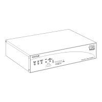
INDICATORS
Power on LED: Red
Loop current: A five LED bar graph type meter is provided to allow monitoring of loop current output and
assist in setting up the amplifier. This is provided by monitoring true output current rather than from a line
level derived signal. The calibration is as follows:
PDA200/2: 1st led = 75mA 2nd led = 375mA 3rd led = 1.5A 4th led = 3.75A 5th led = 6A
PDA500/2: 1st led = 112mA 2nd led = 562mA 3rd led = 2.25A 4th led = 5.6A 5th led = 9A
PDA1000/2: 1st led = 150mA 2nd led = 750mA 3rd led = 3A 4th led = 7.5A 5th led = 12A
Accuracy - +-10%
This meter has PPM type characteristics i.e. fast attack and slow release. This allows easy reading of fast peaks.
Compression: A two LED display is provided for indication of signal compression. The first LED shows the
beginning of compression whilst the second indicates very high compression levels have been reached.
REAR PANEL CONTROLS
On/Off switch incorporated into IEC mains inlet.
Four way piano key style DIP switch selects Phantom power for mic 1 & 2 XLR inputs and switches XLR input
1 between Line and Microphone settings. The fourth of the 4-in-line switch is not connected.
FRONT PANEL CONTROLS
Level controls for XLR 1 (Line/Mic switchable), XLR 2 (Mic) and Outreach.
These can be used individually or any of them together, in which case they act as a three input mixer.
Drive control: Sets level of amplifier output current supplied by the amplifier. Analogous to the volume
control on a standard voltage output amplifier but NOT designed to be adjusted once set to the correct
value for any given installation.
Metal compensation control. When fully anti-clockwise has no effect on the signal. When turned clockwise
imparts a rising 3dB/octave characteristic to the frequency response of the amp. This tends to counteract the
effect of metal in proximity to the loop. Where there is some distance between the loop and any metal, or
the quantity of metal is small, an intermediate setting of the control should be found which provides a
satisfactory tonal balance.
COOLING REQUIREMENTS
The PDA1000/2 and PDA500/2 have thermostatically controlled cooling fans, which are activated when the
amplifier’s internal heatsink temperature reaches approximately 56
o
C. It is therefore normal for the fans to
be heard switching on and off in everyday use.
The PDA200/2 model does not require a cooling fan, as it does not generate as much heat as the larger models.
In all cases the amplifiers should be operated in a cool environment, away from sources of heat and should
never be covered with any object that could impede the flow of cooling air.
DIMENSIONS & WEIGHT
All models: Length – 380mm; Depth – 220mm; Height – 80mm
Weight: PDA200/2 – 3.74Kg, PDA500/2 – 3.46Kg; PDA1000/2 – 4.54Kg