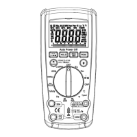
2.
Set the rotary switch at desired
A
.:
or
A
-
range position and connect test leads in series
with the load under measurement.
3.
Read LCD display. The polarity of red lead connection will be indicated when making a DC
measurement.
4.
When only the figure
"1"
displayed, it indicates overrange situation and the higher range has
to be selected.
3.3
MEASURING RESISTANCE
1.
Connect the black test lead to the COM jack and the red teas lead to the
Via
jack.
(NOTE:
The polarity of the red lead connection is positive
"
+
")
2.
Set the rotary switch at desired Cl range position and connect test leads across the
resistance under measurement. Read LCD display.
NOTE:
1.
For resistance above
1
MCl, the meter may take a few seconds to stabilize reading.
 Loading...