1
3
4
2
5
6
2
2
7
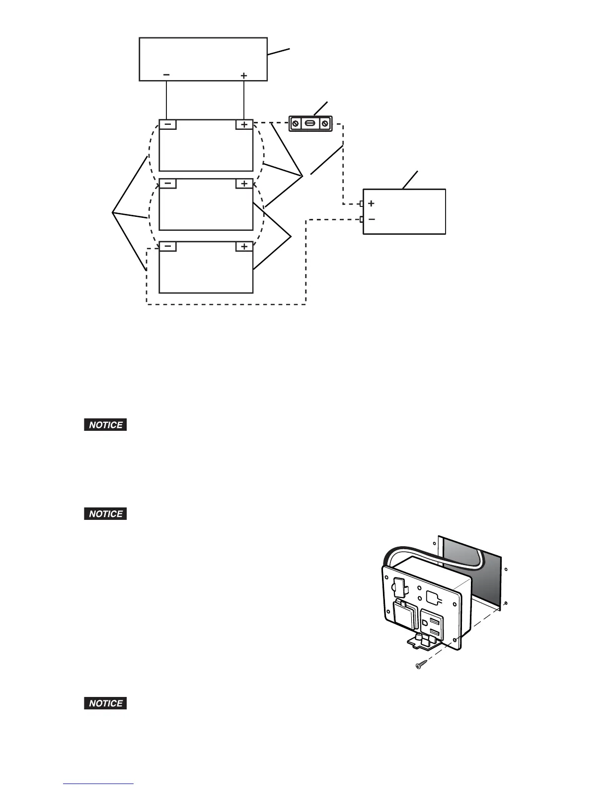
Leg
end
1. Battery Charging Source
2. 12-volt Batteries
3. 200-amp ANL Fuse
4. Power Inverter
5. Negative (-) Cable (see SPECIFICATIONS for cable requirements)
6. Positive (+) Cable (see SPECIFICATIONS for cable requirements)
7. Additional Batteries Connected in Parallel Circuit
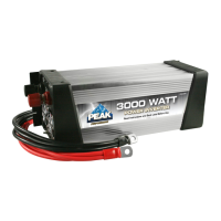
Installation of Remote Outlet
If y
ou are not comfortable with 12-volt DC vehicle wiring or with the mounting of the
remote outlet, have it professionally installed.
1. Make sure the Inverter ON/OFF switch is in the OFF position.
2. Determine the desired location for mounting the remote outlet, keeping in mind that you must
route the remote outlet 110/120-volt AC cord and remote outlet connector cable to where the
Inverter is mounted. It must not be more than 10 ft (3 m) away from where the Inverter is mounted.
3. Remove the template for cutting the hole from the middle of this manual.
4. Tape the template to the location chosen for mounting the remote outlet.
Before you begin cutting or drilling, you must check what is behind the mounting
location. If there are any vehicle components or wiring behind the mounting location, you
must take precautions not to damage them.
5. Cut the square hole using the shaded area of the template
POWER
F
AULT
ON/OFF
as a guide.
6. Insert the remote outlet in the hole and mark the four holes
for the mounting screws.
7. Drill the four holes for the mounting screws.
8. Secure the remote outlet using four screws.
9. Carefully route the cord and the cable to the Inverter, being
careful to not interfere with any vehicle components or
existing wiring.
10. Secure the cord and cable in place with tape or wire ties if needed.
11. Insert the three-prong plug into one of the Inverter’s 110/120-volt
AC outlets, and plug the remote outlet connector into the remote
outlet port on the Inverter.
USB P
ower Outlet Operation
The USB power outlets do not support data communications. The outlets have a
maximum of 5 volts/2.1 A.
1. Plug the USB-powered device into a USB power outlet.
2. Make sure the Inverter is correctly connected to the battery.