EasyManua.ls Logo

Peak PKC0RB Rx User Manual

Peak PKC0RB Rx
9 pages
To Next Page IconTo Next Page
Page #1 background imageLoading...
Page #1 background image
Wireless Rear View Backup System
I. Product functions
The product is mainly used for backing or parking a car. It is composed of a transmitter and a receiver, and is
attached with a retaining bracket and the power core.
The transmitter adopts 2.4G Digital wireless backing and rear viewing approach, and the receiver adopts 3.5” LCD
2.4G Digital wireless backing and rear viewing approach. The transmitter shoots the image through CMOS image
sensor and converts such image into digital signal before sending it out, then the receiver restores the received digital
signal into image and displays it on the LCD screen, so that the accuracy and safety are ensured when the driver is
backing or parking a car.
II. Precautions in safety operation of the product
The receiver is installed on the console or windshield of the car. Please install it firmly and keep the LCD screen
free from impacts. The transmitter is installed at the tail of the car and is fastened in a right position. Keep the CMOS
camera clean to ensure that reliable information is provided to the driver.
III. Component list
S/N
Name
Photo
Quality
required
1
Receiver
1
2
Transmitter
1
3
Retaining
bracket of
the receiver
1
4.
Power core
of the
receiver
1
PKC0BU4 Tx & PKC0RB Rx
Question and Answer IconNeed help?

Do you have a question about the Peak PKC0RB Rx and is the answer not in the manual?

Peak PKC0RB Rx Specifications

General IconGeneral
WirelessYes
Compatible ModelsUniversal
MaterialPlastic
ColorBlack
Screen Size3.5 inches

Summary

Product Overview and Operation

Product Description and Function

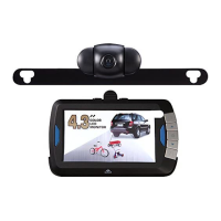
The product is mainly used for backing or parking a car, composed of transmitter and receiver.

System Operating Principle

Transmitter shoots image via CMOS sensor, sends digital signal to receiver for display on LCD screen.

Safety Precautions for Operation

Install receiver firmly, keep LCD screen free from impacts, keep camera clean for clear information.

Component Identification

Lists main components: Receiver, Transmitter, Retaining bracket, Power core for the receiver.

Receiver Power and Indicators

Receiver uses 12V/24V DC. Blue indicator is lit when powered; flashes if no signal.

Receiver Key Controls

Details functions of Menu/Return, Up/Mode, Power/Confirm, Down, and Line buttons.

Pairing the Camera Transmitter

Procedure to pair the camera with the receiver via OSD menu and PAIR key.

Master Camera and Code Management

Select master camera priority, clear paired codes, and mirror/rotate display options.

Image Display Adjustments

Adjust brightness, contrast, and color for optimal image display on screen.

Software Version and Screen Indicators

Query software version and understand on-screen icons for status and signal.

Camera Transmitter Features

Covers power connection, pairing, limits, auto-triggering, and night vision.

Product Installation and Compliance

Receiver Installation Steps

Install retaining bracket on receiver, then mount receiver on car console or windshield.

Receiver Power Connection

Connect receiver power cord to host and plug into cigar lighter socket.

Transmitter Installation

Install transmitter at the tail of the car, connecting to power supply of taillights or interior lighting.

Regulatory Compliance Information

Details FCC and Industry Canada compliance rules and responsibilities.

Antenna and RF Exposure Guidelines

Specifies antenna type, max gain, and minimum distance for RF exposure compliance.

Related product manuals