ASAHI/AMERICA, INC 655 ANDOVER STREET LAWRENCE, MA. 01843 TELEPHONE 800-343-3618
Location: assembly/manuals Series 92 A/C Modulating Svc Manual Gen II Rev. A 11/15/19
Page 5 of 26
Installation
Electrical
Reference Drawing #289S92
Models S-92, A92, & B92
1A. To gain access to terminal strip (Part #24) it is necessary to remove manual
override knob (Part #18) by loosening slotted setscrew (Part #39). Remove 2
cover screws and cover; the remaining 6 cover screws are packaged inside
the actuator.
Model C92
1B. To gain access to terminal strip it is necessary to remove manual override
hand wheel (Part #18A) by loosening slotted setscrew (Part #39). Remove
cam (Part #51) by loosening 2 set screws (Part #52). Remove 2 cover screws
and cover; the remaining 6 cover screws are packaged inside the actuator.
All Models
2. Make electrical connections to terminal strip as shown on wiring schematic
located inside the cover (per various electrical codes there is a green screw
on the actuator base plate for grounding purposes). All units are completely
calibrated prior to shipment, and no internal adjustments should be required.
3. Install 1/2" NPT conduit fitting(s) to actuator base. Please ensure that proper
conduit fitting is used to maintain enclosure rating (weatherproof, explosion proof
or combination weather proof/explosion proof).
NOTE: We recommend sealing conduit openings on units installed outdoors or
exposed to large temperature swings (15ºF or more).
We also recommend the heater and thermostat option in these applications.
4. Replace actuator (gasket if removed) cover, and install 8 cap screws supplied
and tighten securely. For outdoor or wet locations it is recommended prior to
replacing the cover that the top shaft seal be cleaned and coated with silicone
grease. Also clean shaft and lightly coat seal area of shaft with silicone
grease. Unit is now ready for operation.
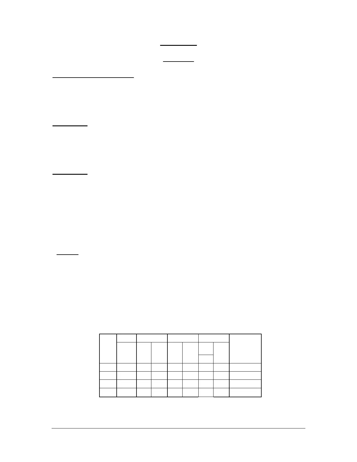
Cycle Time
per 90
Degrees
NOTE: Amp rating is considered locked rotor.
Duty cycles are for ambient tempe
rature (73°F)
 Loading...


