DHC-100
10 U.S. Patent 7,466,100 applies to this product PEAKTRONICS
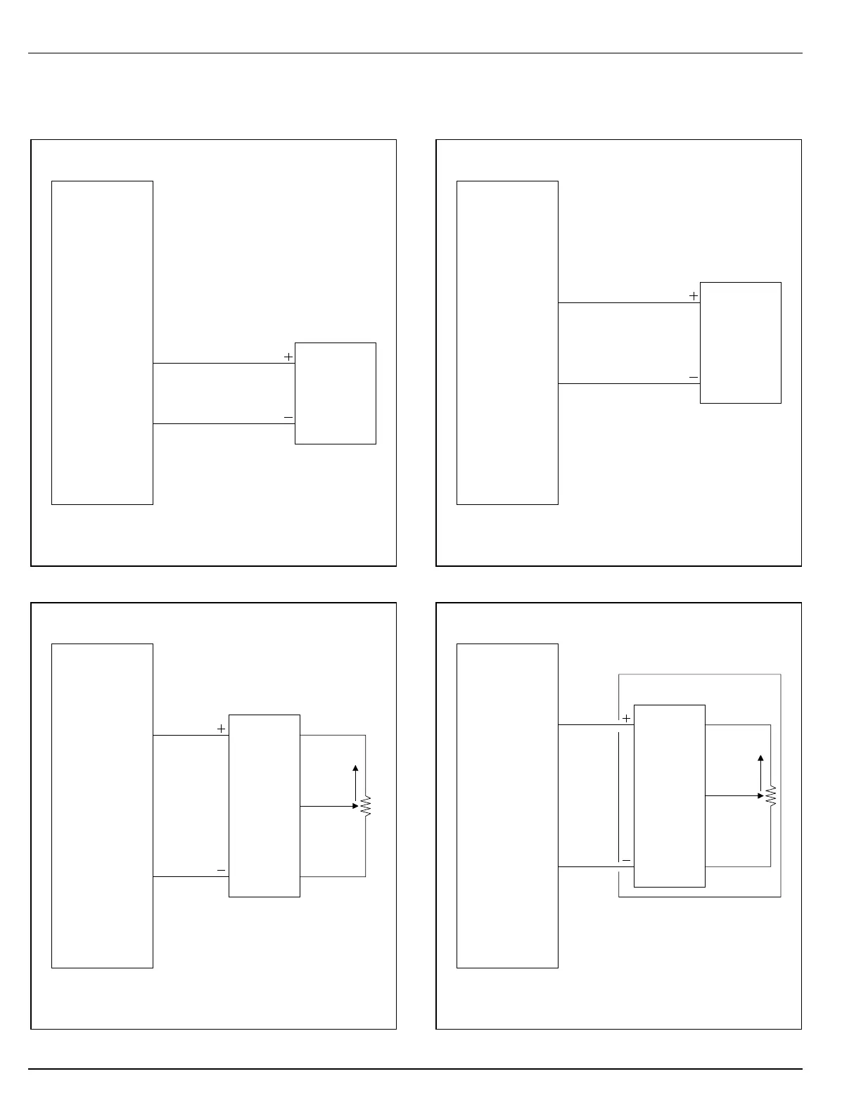
WIRING DIAGRAMS
Input Signal Configurations
4-20mA Input using a self powered transmitter
DHC-100
4-20mA
Sourcing
or
Sinking
output
J2-5
4-20mA
SIGNAL GND
J2-4
135 ohm Slide Wire
using the 4-20mA Input Signal
DHC-100
XMA-108
135 ohm
Slide
Wire
4-20mA
Transmitter
OPEN
+15V OUT
J2-8
4-20mA
J2-5
Voltage Input using digital-to-analog card
DHC-100
VOLTAGE CMD (+)
J2-6
SIGNAL GND
J2-4
0-5V
1-5V
0-10V
or
2-10V
DAC
Remote Command Pot
using the 4-20mA Input Signal
DHC-100
MLT-100A
XMA-104A
Command
Pot
4-20mA
Transmitter
(includes dial and knob)
CW
RED
WHT
BLK
+15V
OUT
J2-8
4-20mA
J2-5

 Loading...

