ASAHI/AMERICA, INC 655 ANDOVER STREET LAWRENCE, MA. 01843 TELEPHONE 800-343-3618
Location: assembly/manuals Series 92 A/C Modulating Svc Manual Gen II Rev. A 11/15/19
Page 22 of 26
Series 92 Options Codes for Serial # Tags
Example 1: S92HTPW
NEMA Type 4X enclosure, heater & thermostat and feedback potentiometer
installed.
Example 2: AM92C1XW
UL1203 Explosion Proof enclosure, mechanical brake and 4-20mA positioner
installed.
Specifications
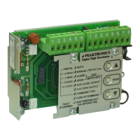
DHC-100 Specs
POWER REQUIREMENTS
DHC-100: 117VAC 10%, 50/60 Hz
DHC-100A: 234VAC 10%, 50/60 Hz
DHC-100B: 24VAC 10%, 50/60 Hz
12 VA typical (not including output load)
Fuse Type: 6.3A TR5 Time delay (replaceable)
COMMAND SIGNAL INPUT
Input Impedance
20K ohms (VOLTAGE COMMAND (+) Input)
251 ohms 1% (4-20 mA CMD (+) Input)
Loss of Command threshold
< 0.75V (1-5 VDC input)
< 1.5V (2-10VDC input)
< 3mA (4-20mA input)
Command Out of Range Threshold
>5.24V (0-5VDC, 1-5VDC input)
>10.5V (0-10VDC, 2-10VDC input)
>21mA (4-20mA input)

 Loading...